Table of Contents
Advertisement
Quick Links
Operating Instructions
Functional Manual
Interface Board for 12G-SDI Optical
Commercial Use
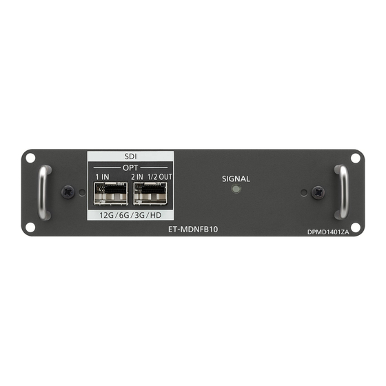
ET-MDNFB10
Model No.
Thank you for purchasing this Panasonic product.
■ Before using this product, please read these "Operating Instructions" and the "Operating
Instructions" of the projector carefully and save the manuals for future use.
■ Before using this product, be sure to read "Read this first!" ( x page 3).
ENGLISH
DPQP1310ZA/X1
Advertisement
Table of Contents

Related Manuals for Panasonic ET-MDNFB10


Summary of Contents for Panasonic ET-MDNFB10
- Page 1 Commercial Use ET-MDNFB10 Model No. Thank you for purchasing this Panasonic product. ■ Before using this product, please read these “Operating Instructions” and the “Operating Instructions” of the projector carefully and save the manuals for future use. ■ Before using this product, be sure to read “Read this first!” ( x page 3).
-
Page 2: Table Of Contents
Contents Contents Read this first! Precautions for use Supported projector Supported SFP module Handling of the product Disposal Accessories Part names and functions Installing the Interface Board Before installing or removing the Interface Board How to install the Interface Board How to remove the Interface Board Installing the SFP module How to install the SFP module... -
Page 3: Read This First
The laser beam may enter the eyes and cause damage to the eyes. Importer’s name and address within the European Union Panasonic Marketing Europe GmbH Panasonic Testing Centre Winsbergring 15, 22525 Hamburg, Germany... -
Page 4: Precautions For Use
Prepare the commercially available SFP module and the optical fiber cable required for connection according to the usage, video signal to be input, specification of the external device to be connected, etc. f The SFP module that the operation has been verified with the Panasonic projector can be confirmed from the following URL. https://panasonic.net/cns/projector/ Confirmation of operation for SFP module from other manufacturer has been performed with the items set by Panasonic Corporation, and not all the operations are warranted. -
Page 5: Accessories
Precautions for use Accessories Make sure that the following accessories are provided with the product. Numbers enclosed in < > show the number of accessories. Port cover <2> Screw <4> (DVHR1128ZA/X1) (XSB3+8FN) (Attached to the product at the time of purchase) Attention f After unpacking the product, discard the packaging material properly. -
Page 6: Installing The Interface Board
Installing the Interface Board Installing the Interface Board Requesting a qualified technician to install or remove the Interface Board to the projector is recommended. A malfunction may occur due to static electricity. Consult your dealer. Before installing or removing the Interface Board f Always turn off the power of the projector before installing or removing the Interface Board. -
Page 7: How To Remove The Interface Board
Installing the Interface Board How to remove the Interface Board Handle Fig. 1 Remove the Interface Board. (Fig. 1) f Remove the four screws fixing the Interface Board by rotating counterclockwise with a Phillips screwdriver. The removed screws are used to fix the slot cover. f Hold the handle of the Interface Board and remove it slowly. -
Page 8: Installing The Sfp Module
Installing the SFP module Installing the SFP module This section explains an example of a procedure to install and remove the SFP module. Please also check the operating instructions and setup guide of the SFP module to be installed. How to install the SFP module SFP ports SFP modules Circuit boards... - Page 9 Installing the SFP module Remove the SFP module. (Fig. 2) f Hold the lever and slowly pull out the SFP module. Attention f Make sure to attach the port cover on the SFP port that the SFP module is not installed. f Store the removed SFP module with the protection cap, etc., attached so that dust does not accumulate or the SFP module does not get dirty.
-
Page 10: Connecting Example
Connecting example Connecting example 12G-SDI signal output compatible device HD-SDI signal, 3G-SDI signal, 6G-SDI signal, or 12G-SDI signal SDI - optical converter Optical fiber cable Note f Prepare the commercially available SFP module and the optical fiber cable required for connection according to the usage, video signal to be input, specification of the external device to be connected, etc. -
Page 11: Selecting The Input Signal
Selecting the input signal Selecting the input signal The method to switch the input of the image to project is as follows. f Press the input selection button on the remote control or the control panel of the projector and directly specify the input of the image to project. -
Page 12: Menu Navigation
Menu navigation Menu navigation This section explains about the on-screen menu (menu screen) that can be operated by installing this Interface Board in the slot of the projector. For the menu items with l in the following table, the additional explanation for the target model is described. Refer to the explanation together with the “Operating Instructions”... -
Page 13: [Slot In]
Menu navigation Note f The backup function is enabled when [BACKUP INPUT MODE] is set to anything other than [OFF] and same signal is input to the primary input and the secondary input. f To switch to the backup input signal using the backup function, make sure that the following three conditions are satisfied to be ready to use the function. - Page 14 Menu navigation Press the <ENTER> button. f The [SLOT IN] screen is displayed. Press as to select [SDI OPT1] or [SDI OPT2], and press the <ENTER> button. f The detailed setting screen for the selected item is displayed. Press as to select [SDI MAPPING]. Press qw to switch the item.
-
Page 15: [Startup Input Select]
Menu navigation [12-bit] Fixes to [12-bit]. [10-bit] Fixes to [10-bit]. Setting [SIGNAL LEVEL] in [SLOT IN] (OPT input) Select [DISPLAY OPTION] from the main menu. Press the <ENTER> button. f The [DISPLAY OPTION] screen is displayed. Press as to select [SLOT IN]. Press the <ENTER>... - Page 16 Menu navigation Press qw to switch the item. f The items will switch each time you press the button. [OFF] Disables the schedule function. Enables the schedule function. Refer to “How to assign a program” (x page 16) or “How to set a [ON] program”...
-
Page 17: [Remote2 Mode]
Menu navigation Detailed settings of [COMMAND] Description [COMMAND] [SDI OPT1 [SLOT1]] Switches the input to SDI OPT1 of the Interface Board. [SDI OPT2 [SLOT1]] Switches the input to SDI OPT2 of the Interface Board. [SDI OPT1 [SLOT2]] Switches the input to SDI OPT1 of the Interface Board. [INPUT] [SDI OPT2 [SLOT2]] Switches the input to SDI OPT2 of the Interface Board. -
Page 18: [Multi Display]
Menu navigation [MULTI DISPLAY] Four images can be displayed simultaneously by dividing the projection screen into four. The multi-display function setting can be saved to [USER1], [USER2], or [USER3]. Select [MULTI DISPLAY] from the main menu. Press the <ENTER> button. f The [MULTI DISPLAY] screen is displayed. -
Page 19: [Control Device Setup]
Menu navigation [CONTROL DEVICE SETUP] Enable/disable the button operations on the control panel and the remote control of the projector. Select [SECURITY] from the main menu. Press the <ENTER> button. f The [SECURITY] screen is displayed. Enter the security password set on the projector, and press the <ENTER> button. Press as to select [CONTROL DEVICE SETUP]. - Page 20 Menu navigation f If the operations of both [CONTROL PANEL] and [REMOTE CONTROL] are set to [DISABLE], the projector cannot be turned off (cannot enter standby). f When the setting has completed, the menu screen will disappear. To operate continuously, press the <MENU> button to display the main menu.
-
Page 21: Appendix
Appendix Appendix Troubleshooting Review the following points. Problems Points to be checked f Is the SFP module installed correctly? f Is the optical fiber cable connected correctly? The OPT input image is not displayed. f Is a signal not supported by this Interface Board or the SFP module input? f Is there dust or dirt on the connector of the SFP module or the optical fiber cable? Cannot switch to the input f Is the Interface Board correctly installed in the slot? -
Page 22: List Of Compatible Signals
Appendix List of compatible signals The following table describes the video signals supported by this Interface Board. This Interface Board supports only the single link SDI signal. The dual link SDI signal and the quad link SDI signals are not supported. Also, the image may not display correctly depending on the specification of the SFP module in use. - Page 23 Appendix Scanning freq. Dot clock Signal name Resolution freq. Format Color format Sampling Horizontal Vertical (SIGNAL FORMAT) (Dots) division (MHz) (kHz) (Hz) 2 048 x 1 080 28.1 25.0 74.3 ― 3G-SDI Level-A 4:4:4 10bit 2 048 x 1 080 28.1 25.0 74.3...
- Page 24 Appendix Scanning freq. Dot clock Signal name Resolution freq. Format Color format Sampling Horizontal Vertical (SIGNAL FORMAT) (Dots) division (MHz) (kHz) (Hz) 4 096 x 2 160 67.5 30.0 297.0 6G-SDI Type 2 4:2:2 10bit 4 096 x 2 160 67.5 30.0 297.0...
-
Page 25: Specifications
Note f “SLOT NX” is a name of the slot unique to Panasonic supporting the signal input for the 4K image. f For the video signals supported by this Interface Board, refer to “List of compatible signals” (x page 22). - Page 26 This symbol is only valid in China. Panasonic Corporation Web Site : https://panasonic.net/cns/projector/ © Panasonic Corporation 2020 Panasonic System Solutions Company of North America Two Riverfront Plaza, Newark, NJ 07102 TEL: (877) 803 - 8492 Panasonic Canada Inc. 5770 Ambler Drive, Mississauga, Ontario L4W 2T3...
Need help?
Do you have a question about the ET-MDNFB10 and is the answer not in the manual?
Questions and answers