Table of Contents
Advertisement
Quick Links
Advertisement
Table of Contents

Subscribe to Our Youtube Channel
Related Manuals for Laguna Tools SHEARTEC II


Summary of Contents for Laguna Tools SHEARTEC II
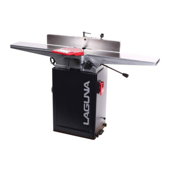
- Page 1 6" WEDGEBED JOINTER SHEARTEC II MANUAL LAGUNA TOOLS 2072 Alton Parkway Irvine, California 92606 Ph: 800.234.1976 www.lagunatools.com © 2018, Laguna Tools, Inc. LAGUNA® and the LAGUNA Logo® are the registered trademarks of Laguna Tools, Inc. All rights reserved.
-
Page 2: Table Of Contents
Table of contents SAFETY INSTRUCTIONS ........................2 RECEIVING T HE JOINTER ....................... 4 INSTALLATION ............................. 4 MOUNTING JOINTER TO STAND..................... 5 CUTTERHEAD GUARD I NSTALLATION & REMOVAL ..............6 INSTALLING DUST CHUTE ........................ 6 GROUNDING INSTRUCTIONS ......................7 SAFETY SWITCH ..........................8 ADJUSTMENTS ............................ -
Page 3: Safety Instructions
SAFETY INSTRUCTIONS For Your Safety Read Instruction Manual Before Operating Jointer As with all machines, there is a certain amount of hazard involved with the use of this jointer. Use the machine with the respect and caution demanded where safety precautions are concerned. When normal safety precautions are overlooked or ignored, personal injury to the operator can result. - Page 4 Use recommended accessories. Consult the owner’s manual for recommended accessories. The use of improper accessories may cause risk of injury to persons. Never stand on tool. Serious injury could occur if the tool is tipped or if the cutting tool is unintentionally contacted.
-
Page 5: Receiving T He Jointer
RECEIVING T HE JOINTER Upon delivery, open shipping containers and check that all parts are in good condition. Any damage should be reported to your distributor and shipping agent immediately. Before proceeding further, read your manual and familiarize yourself thoroughly with assembly, maintenance and safety procedures. -
Page 6: Mounting Jointer To Stand
MOUNTING JOINTER TO STAND Position the jointer on the stand so that the pulley attached to the cutterhead on the jointer is directly above and on the same side as the motor pulley. Use three lock bolts and spring washers to firmly fasten the jointer to the stand. -
Page 7: Cutterhead Guard I Nstallation & Removal
CUTTERHEAD GUARD I NSTALLATION & REMOVAL WARNING: Use the jointer guard for ! al l o perations 1. Disconnect jointer from power source. 2. Turn knob (A) counterclockwise to create tension on spring, and hold it there. See Figure 6 3. -
Page 8: Grounding Instructions
must be reconnected for use on a different type of GROUNDING INSTRUCTIONS electric circuit, the reconnection should be made by WARNING: If the machine does not come qualified service personnel and after reconnection, the wired to run, the electricals and motor !... -
Page 9: Safety Switch
SAFETY SWITCH The jointer is equipped with a push-button switch that will accept a safety padlock (not included). See Figure 10. T o safeguard your machine from unauthorized operation and accidental starting by young children, the use of a padlock is required. ADJUSTMENTS FIGURE 10 Tools required... -
Page 10: Installing New Knives
INSTALLING NEW KNIVES STANDARD BLADES CUTTERHEAD Unplug or disconnect jointer from power source and lock out power. When installing new knives remove only one knife at a time. Clean the knife slot and install the new knife. Adjust and lock new knife in cutterhead assembly before proceeding to next knife. - Page 11 Now place it on the outfeed table to the rear of the cutterhead with the flat indicator point over the cutterhead (Figure 17) Insert a hex wrench into the jack screw and rock the cutterhead back and forth. Watch the pointer on the knife-setting gauge.
-
Page 12: Sheartec 2 Cutterhead
CUTTERHEAD REMOVAL SHEARTEC 2 CUTTERHEAD If removal of the cutterhead is necessary, do Knife inserts are dangerously sharp. WARNING: the following: Use extreme caution when inspecting, removing or replacing knife inserts. WARNING: Disconnect jointer from ! power source. The knife inserts on the Jointer are four-sided. When dull, simply remove each insert, rotate it 1. -
Page 13: Depth Of Cut
DEPTH OF CUT Depth of cut is determined by the height of the infeed table relative to the high point of the knives on the cutterhead. When facing the width of a board (as opposed to the edge of a board), NEVER attempt to take off more than 1/64"... -
Page 14: Fence Adjustments: Tilt
TABLE GIBS AND LEVELING The table gibs on your machine are factory adjusted and may never require readjustment. Should any adjustment become necessary, do the following: 1. Lightly loosen the gib adjusting screws (A), Figure 23. By loosening the lock nuts first the set screws should be loose enough to move the table. - Page 15 Fence Stop Adjustments Periodically check the 90° and 45° backward (135°) tilt accuracy of the fence with an angle measuring device, such as an adjustable square or machinist’s protractor. 90º Fence Adjustment Referring to Figure 24A: The 90º stop is controlled by the stop bolt (E) and the stop plate (C).
-
Page 16: Basic Operations
two handed push BASIC OPERATIONS block Before m aking any c uts on t he s tock, m ake a f ew practice cuts by r aising t he i nfeed t able to “ 0" a nd with the power disconnected. In this manner you will acquaint yourself with the feel of jointer operations. - Page 17 left hand pushes SURFACING: L ONG BOARDS down toward fence as right hand The use of push blocks w ill help to i nsure starts feed against hands coming in contact with cutterhead in the event of a kickback and as trailing end of board passes over cutterhead.
- Page 18 move fence forward JOINTING (or EDGING) to expose only amount of cutterhead required Never edge a board that is less than 3 inches wide, less than 1 /4 inch thick, or 12 inches long, w ithout using a push block. CAUTION: When workpiece is twice the è...
- Page 19 SKEWING ( SHEAR CUTTING) When edging or facing burl or birds-eye maple, it is not unusual to deface or mar the surface being finished. This i s caused b y the cutterhead b lades a t times cutting against the grain.
-
Page 20: Parts Diagrams
PARTS DIAGRAMS... -
Page 23: Parts List
PARTS LIST Part No. Descriptions Q'ty 1 360034-901 KNOB FENCE 2 006002-091 FLAT WASHER 3 380209-901 T-NUT 4 051131-000 HOLDER FENCE 5 290003-901 BOLT SHOULDER 6 170047-901 PLATE STOP 7 006002-097 FLAT WASHER 13.5*40*3.0t 8 011002-103 SPRING PIN 4*12 9 380080-000 10 011002-105 SPRING PIN 4*20... - Page 24 Part No. Descriptions Q'ty 35 003003-205 HEX. SCREW 5/16"-18NC*1" 36 050032-000 TILT PLATE 37 230015-901 STUD PIVOT 38 009022-100 HEX. NUT 3/8"-16NC 39 922884-000 TABLE ASS'Y CSA/UL .1 003104-103 CAP SCREW 5/16"-18NC*3/4" .2 003104-107 CAP SCREW 5/16"-18NC*2" .3 003201-102 SET SCREW 1/4"-20NC*3/8"...
- Page 25 Part No. Descriptions Q'ty 49 920201-000 HANDLE ASS'Y 50 920165-000 HANDWHEEL 51 050065-901 BLOCK ASM DEPTH 52 360033-901 PLUNGER 53 280010-000 SPRING 54 380085-901 HOUSING PLUNGER 55 230156-615 KNOB PLUNGER 22*1/4"-20NC 56 230016-000 LOCK HANDLE 60 006307-100 LOCK WASHER 10.2*18.5 61 003006-301 HEX.
- Page 26 Part No. Descriptions Q'ty 70 002301-201 RIVET 71 920155-000 CUTTERHEAD GUARD ASS'Y 72 170045-901 RETAINER 73 280009-000 SPRING 74 110024-000 KNOB 75 110004-000 RETAINING KNOB 76 003305-206 PAN HD SCREW 5/32"-32NC*5/8" KNIFE SETTING GAUGE ASS'Y FOR 79 920206-000 STANDARD CUTTERHEAD 87 040003-000 HEX.
- Page 27 Part No. Descriptions Q'ty 118 900758-000 MOTOR ASS'Y 1.5HP.1PH .1 603067-000 MOTOR 1.5HP*1PH .2 012003-010 5*5*30 .3 050021-901 MOTOR PULLEY .4 003201-102 SET SCREW 1/4"-20NC*3/8" .5 021316-000 STRAIN RELIEF MG16A-10B-ST .6 473003-006 MOTOR CORD SJT14AWG*3C*750mm 119 003003-203 HEX. SCREW 5/16"-18NC*3/4" 120 014102-000 V-BELT 121 006307-100...
- Page 28 Laguna Tools is not responsible for errors or omissions. Specifications subject to change. Machines may be shown with optional accessories. © 2018, Laguna Tools, Inc. LAGUNA® and the LAGUNA Logo® are the registered trademarks of Laguna Tools, Inc. All rights reserved.
Need help?
Do you have a question about the SHEARTEC II and is the answer not in the manual?
Questions and answers