Table of Contents
Advertisement
Quick Links
Advertisement
Table of Contents

Subscribe to Our Youtube Channel
Related Manuals for KROHNE POWERFLEX 2200 C


Summary of Contents for KROHNE POWERFLEX 2200 C
- Page 1 POWERFLEX 2200 C/F/S/D POWERFLEX 2200 C/F/S/D POWERFLEX 2200 C/F/S/D POWERFLEX 2200 C/F/S/D Handbook Handbook Handbook Handbook Guided Radar (TDR) Level Transmitter for the nuclear industry © KROHNE 10/2016 - 4005314002 - MA POWERFLEX 2200 R02 en...
- Page 2 All rights reserved. It is prohibited to reproduce this documentation, or any part thereof, without the prior written authorisation of KROHNE Messtechnik GmbH. Subject to change without notice. Copyright 2016 by KROHNE Messtechnik GmbH - Ludwig-Krohne-Str. 5 - 47058 Duisburg (Germany) www.krohne.com 10/2016 - 4005314002 - MA POWERFLEX 2200 R02 en...
-
Page 3: Table Of Contents
CONTENTS POWERFLEX 2200 C/F/S/D 1 Safety instructions 1.1 Software history ....................... 7 1.2 Intended use ........................7 1.3 Certification ........................7 1.4 Electromagnetic compatibility ..................8 1.5 Safety instructions from the manufacturer ..............9 1.5.1 Copyright and data protection ....................9 1.5.2 Disclaimer .......................... - Page 4 CONTENTS POWERFLEX 2200 C/F/S/D 4 Electrical connections 4.1 Safety instructions......................46 4.2 Electrical installation: 2-wire, loop-powered ..............46 4.2.1 Compact version ........................46 4.2.2 Remote version ........................48 4.3 Remote device data ......................49 4.3.1 Requirements for signal cables supplied by the customer ..........49 4.3.2 How to prepare a signal cable supplied by the customer............
- Page 5 CONTENTS POWERFLEX 2200 C/F/S/D 6.5 Status and error messages.................... 92 6.5.1 Device status (markers)......................92 6.5.2 Error handling........................94 7 Service 7.1 Periodic maintenance....................100 7.2 Keep the device clean....................100 7.3 How to replace device components ................100 7.3.1 Service warranty ......................... 100 7.4 Availability of services ....................
- Page 6 CONTENTS POWERFLEX 2200 C/F/S/D ® 9.10 HART menu tree for AMS..................132 9.10.1 Overview AMS menu tree (positions in menu tree) ............132 9.10.2 AMS menu tree (details for settings)................132 9.11 HART® menu tree for PDM..................134 9.11.1 Overview PDM menu tree (positions in menu tree)............134 9.11.2 PDM menu tree (details for settings) ................
-
Page 7: Safety Instructions
SAFETY INSTRUCTIONS POWERFLEX 2200 C/F/S/D 1.1 Software history "Firmware revision" agrees with NAMUR NE 53. It is a series of numbers used to record the revision status of embedded software (firmware) in electronic equipment assemblies. It gives data on the type of changes made and the effect that changes have on compatibility. -
Page 8: Electromagnetic Compatibility
SAFETY INSTRUCTIONS POWERFLEX 2200 C/F/S/D 1.4 Electromagnetic compatibility The device design agrees with the Electromagnetic Compatibility (EMC) Directive and the related European Standard when installed in metallic tanks. The device design agrees with tests done according to performance criteria "A" of International Standards IEC 61000 (Parts 4-2, 4-4, 4-5, 4-6, 4-8, 4-9, 4-10, 4-12, and 4-16), and CISPR 11. -
Page 9: Safety Instructions From The Manufacturer
SAFETY INSTRUCTIONS POWERFLEX 2200 C/F/S/D 1.5 Safety instructions from the manufacturer 1.5.1 Copyright and data protection The contents of this document have been created with great care. Nevertheless, we provide no guarantee that the contents are correct, complete or up-to-date. -
Page 10: Product Liability And Warranty
SAFETY INSTRUCTIONS POWERFLEX 2200 C/F/S/D 1.5.3 Product liability and warranty The operator shall bear responsibility for the suitability of the device for the specific purpose. The manufacturer accepts no liability for the consequences of misuse by the operator. Improper installation or operation of the devices (systems) will cause the warranty to be void. The respective "Standard Terms and Conditions"... -
Page 11: Warnings And Symbols Used
SAFETY INSTRUCTIONS POWERFLEX 2200 C/F/S/D 1.5.5 Warnings and symbols used Safety warnings are indicated by the following symbols. DANGER! This warning refers to the immediate danger when working with electricity. DANGER! This warning refers to the immediate danger of burns caused by heat or hot surfaces. -
Page 12: Device Description
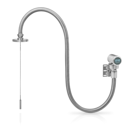
Do a check of the packing list to make sure that you have all the elements given in the order. POWERFLEX 2200 C – Compact version Figure 2-1: Scope of delivery (POWERFLEX 2200 C – Compact version) 1 Device (compact version: signal converter and probe) 2 Quick Start 3 DVD-ROM. - Page 13 DEVICE DESCRIPTION POWERFLEX 2200 C/F/S/D POWERFLEX 2200 S – Compact version with sensor extension Figure 2-2: Scope of delivery (POWERFLEX 2200 S – Compact version with sensor extension) 1 Signal converter 2 Sensor extension: Coaxial cable and support with one attached length of flexible stainless steel jacket...
- Page 14 DEVICE DESCRIPTION POWERFLEX 2200 C/F/S/D POWERFLEX 2200 F – Remote version Figure 2-3: Scope of delivery (POWERFLEX 2200 F – Remote version) 1 Signal converter 2 Quick Start 3 DVD-ROM. This contains the handbook, the quick start, the technical data sheet and related software.
- Page 15 DEVICE DESCRIPTION POWERFLEX 2200 C/F/S/D POWERFLEX 2200 D – Remote version with sensor extension Figure 2-4: Scope of delivery (POWERFLEX 2200 D – Remote version with sensor extension) 1 Signal converter 2 Quick Start 3 DVD-ROM. This contains the handbook, the quick start, the technical data sheet and related software.
-
Page 16: Device Description
DEVICE DESCRIPTION POWERFLEX 2200 C/F/S/D 2.2 Device description The TDR level transmitter is designed to measure the distance, level and volume of liquids. TDR level transmitters use a probe to guide a signal to the surface of the measured product. The device has a large choice of probes. - Page 17 DEVICE DESCRIPTION POWERFLEX 2200 C/F/S/D Sensor extension (with flexible stainless steel jackets) Sensor extension (with flexible stainless steel jackets) Sensor extension (with flexible stainless steel jackets) Sensor extension (with flexible stainless steel jackets) A sensor extension option is available for the compact or remote version of the device. This option is recommended if the ambient conditions around the process connection are not in the approved limits.
-
Page 18: Visual Check
DEVICE DESCRIPTION POWERFLEX 2200 C/F/S/D 2.3 Visual Check INFORMATION! Inspect the packaging carefully for damages or signs of rough handling. Report damage to the carrier and to the local office of the manufacturer. Figure 2-8: Visual check 1 Device nameplate (for more data, refer to... -
Page 19: Nameplates
DEVICE DESCRIPTION POWERFLEX 2200 C/F/S/D 2.4 Nameplates INFORMATION! Look at the device nameplate to ensure that the device is delivered according to your order. Check for the correct supply voltage printed on the nameplate. 2.4.1 Nameplate Figure 2-10: Compact version (C), compact version with sensor extension (S), remote version (F) and remote version... - Page 20 DEVICE DESCRIPTION POWERFLEX 2200 C/F/S/D Figure 2-11: Remote version or remote version with sensor extension: Nameplate attached to the probe assembly 1 Company web address 2 Country of manufacture 3 Degree of ingress protection (according to EN 60529 / IEC 60529)
-
Page 21: Installation
INSTALLATION POWERFLEX 2200 C/F/S/D 3.1 General notes on installation INFORMATION! Inspect the packaging carefully for damages or signs of rough handling. Report damage to the carrier and to the local office of the manufacturer. INFORMATION! Do a check of the packing list to make sure that you have all the elements given in the order. -
Page 22: Transport
INSTALLATION POWERFLEX 2200 C/F/S/D 3.3 Transport Figure 3-1: How to hold the device: general data Figure 3-2: How to hold the device: cable data 1 Do not wind the cable probes less than 400 mm / 16¨ in diameter. 2 Do not hold the probe when you lift the device. -
Page 23: How To Prepare The Tank Before You Install The Device
INSTALLATION POWERFLEX 2200 C/F/S/D 3.5 How to prepare the tank before you install the device CAUTION! To avoid measuring errors and device malfunction, obey these precautions. 3.5.1 Pressure and temperature ranges Figure 3-3: Pressure and temperature ranges 1 Temperature at the process connection The temperature at the process connection must stay in the temperature range of the gasket material unless the de- vice is a High-Temperature version. -
Page 24: General Information For Nozzles
INSTALLATION POWERFLEX 2200 C/F/S/D Ambient temperature / flange temperature, flange and threaded connection, in °C Figure 3-4: Ambient temperature / flange temperature, flange and threaded connection, in °C Ambient temperature / flange temperature, flange and threaded connection, in °F Figure 3-5: Ambient temperature / flange temperature, flange and threaded connection, in °F 1 Maximum ambient temperature, °C... - Page 25 INSTALLATION POWERFLEX 2200 C/F/S/D CAUTION! Do not put the process connection near to the product inlet. If the product that enters the tank touches the probe, the device will measure incorrectly. Figure 3-6: Do not put the device near to a product inlet 1 The device is in the correct position.
- Page 26 INSTALLATION POWERFLEX 2200 C/F/S/D For single cable and single rod probes: Figure 3-8: Recommended nozzle dimensions for single rod and single cable probes 1 Recommended conditions: h ≤ d, where h is the height of the tank nozzle and d is the diameter of the tank nozzle.
-
Page 27: Installation Requirements For Concrete Roofs
INSTALLATION POWERFLEX 2200 C/F/S/D CAUTION! Install coaxial probes in clean liquids that are not too viscous. 3.5.3 Installation requirements for concrete roofs Figure 3-11: Installation on a concrete roof 1 The diameter, d, of the hole must be greater than the thickness, t, of the concrete. -
Page 28: How To Attach Probes To The Bottom Of The Tank
INSTALLATION POWERFLEX 2200 C/F/S/D Clearance between the probe and other objects in the tank Probe type Empty space (radius, R ), around the probe [mm] [inches] Coaxial Double rod / cable Single rod / cable 3.6.2 How to attach probes to the bottom of the tank If the liquid is agitated or turbulent, you can attach the probe to the bottom of the tank. - Page 29 INSTALLATION POWERFLEX 2200 C/F/S/D Double cable Ø4 mm / 0.16¨ Figure 3-14: How to attach a double cable probe to keep it straight The probe counterweight has a hole with an M8 internal thread. You can also select the appropriate options and attach:...
- Page 30 INSTALLATION POWERFLEX 2200 C/F/S/D Single cable Ø4 mm / 0.16¨ Figure 3-16: How to attach a Ø4 mm / 0.16¨ single cable probe to keep it straight 1 Probe with threaded end 2 Probe with turnbuckle 3 Probe with chuck 4 If you chose a chuck to anchor the probe, we recommend that you fit a ferrule (metal sheath –...
-
Page 31: Installation In Standpipes (Stilling Wells And Bypass Chambers)
INSTALLATION POWERFLEX 2200 C/F/S/D 3.6.3 Installation in standpipes (stilling wells and bypass chambers) Use a standpipe if: • The liquid is very turbulent or agitated. • There are too many other objects in the tank. • The device is measuring a liquid in a tank with a floating roof. -
Page 32: How To Install The Device On The Tank: General Notes
INSTALLATION POWERFLEX 2200 C/F/S/D CAUTION! The standpipe must be electrically conductive. If the standpipe is not made of metal, obey the • instructions for empty space around the probe. For more data, refer to General requirements on page 27 •... -
Page 33: How To Install A Device With A Threaded Connection
INSTALLATION POWERFLEX 2200 C/F/S/D 3.7.2 How to install a device with a threaded connection Equipment needed: • Device • Gasket (not supplied) • 50 mm / 2¨ wrench (not supplied) Figure 3-20: Threaded connection • Make sure the tank connection is level. -
Page 34: How To Install A Cable Probe In The Tank
INSTALLATION POWERFLEX 2200 C/F/S/D 3.7.3 How to install a cable probe in the tank Figure 3-21: Wind cable probes carefully 1 Do not wind cable probes less than 400 mm / 16¨ in diameter. WARNING! If you bend the probe too much, you will damage the device and it will not measure accurately. -
Page 35: Recommendations For Pits And Tanks Made Of Non-Conductive Materials
INSTALLATION POWERFLEX 2200 C/F/S/D 3.7.4 Recommendations for pits and tanks made of non-conductive materials If you have a device with a single rod or a single cable probe and a thread connection, obey these instructions: • Put a metal sheet between the device and the process connection. -
Page 36: How To Turn Or Remove The Signal Converter
INSTALLATION POWERFLEX 2200 C/F/S/D 3.7.5 How to turn or remove the signal converter The converter turns 360°. The converter can be removed from the process connection assembly under process conditions. Figure 3-24: How to turn or remove the signal converter... -
Page 37: How To Attach The Weather Protection To The Device
INSTALLATION POWERFLEX 2200 C/F/S/D 3.7.6 How to attach the weather protection to the device The device and the weather protection option are supplied disassembled in the same box. The weather protection can also be supplied as an accessory. You must attach the weather protection when you install the device. - Page 38 INSTALLATION POWERFLEX 2200 C/F/S/D Figure 3-26: Installation of the weather protection on a vertical signal converter 1 Put the weather protection clamp around the top of the device. 2 Attach the two locking nuts to the threads on the weather protection clamp. Tighten the lock- ing nuts with a 10 mm socket wrench.
- Page 39 INSTALLATION POWERFLEX 2200 C/F/S/D Figure 3-27: Installation of the weather protection on a horizontal signal converter 1 Put the weather protection clamp around the front of the device (the end of the device that is nearest to the cable entry).
-
Page 40: How To Open The Weather Protection
INSTALLATION POWERFLEX 2200 C/F/S/D 3.7.7 How to open the weather protection Figure 3-28: How to open the weather protection 1 Remove the R-clip from the hole at the front of the weather protection cover. 2 Remove the weather protection cover. -
Page 41: How To Install The Device On The Tank: Remote Version
INSTALLATION POWERFLEX 2200 C/F/S/D 3.8 How to install the device on the tank: remote version 3.8.1 Wall support for the remote version Figure 3-29: Wall support for the remote version (attached to the remote converter) 1 Use marks on the wall to help you put the wall support in the correct position. For more data,... - Page 42 INSTALLATION POWERFLEX 2200 C/F/S/D How to attach the wall bracket Figure 3-30: How to attach the wall bracket CAUTION! We recommend that you use LOCTITE 2432 to lock the bolts for the wall bracket. LOCTITE ® ™ ® 2432 is on the PMUC list of approved materials for the nuclear industry.
- Page 43 INSTALLATION POWERFLEX 2200 C/F/S/D Figure 3-31: Dimensions of the wall bracket Dimensions in mm Dimensions [mm] Wall bracket 67.4 126.4 150.4 Dimensions in inches Dimensions [inches] Wall bracket 2.65 4.98 5.92 10/2016 - 4005314002 - MA POWERFLEX 2200 R02 en...
- Page 44 INSTALLATION POWERFLEX 2200 C/F/S/D How to attach the coaxial cable and the flexible metal jacket to the process connection Figure 3-32: How to attach the coaxial cable and the flexible metal jacket to the process connection CAUTION! You must attach the stainless steel jacket to the wall with clamps. We recommend that you...
- Page 45 INSTALLATION POWERFLEX 2200 C/F/S/D 7 Apply LOCTITE® 2432™ to the thread between the 1½ NPT connection and the union nut. 8 Tighten the union nut with a 60 mm wrench. INFORMATION! For more data about how to use LOCTITE 2432 , refer to the related technical data sheet on ®...
-
Page 46: Electrical Connections
ELECTRICAL CONNECTIONS POWERFLEX 2200 C/F/S/D 4.1 Safety instructions DANGER! All work on the electrical connections may only be carried out with the power disconnected. Take note of the voltage data on the nameplate! DANGER! Observe the national regulations for electrical installations! DANGER! For devices used in hazardous areas, additional safety notes apply;... - Page 47 ELECTRICAL CONNECTIONS POWERFLEX 2200 C/F/S/D CAUTION! Use the applicable electrical cables with the cable glands. • Make sure that the current is not more than 5 A or that there is 5 A-rated fuse in the • electrical circuit that energizes the device.
-
Page 48: Remote Version
ELECTRICAL CONNECTIONS POWERFLEX 2200 C/F/S/D Figure 4-4: How to close the terminal compartment cover 1 Put the cover on the housing and push it down. 2 Turn the cover clockwise until it is fully engaged. 3 Tighten the lock screw. -
Page 49: Remote Device Data
ELECTRICAL CONNECTIONS POWERFLEX 2200 C/F/S/D 4.3 Remote device data 4.3.1 Requirements for signal cables supplied by the customer Basic properties • Twisted cable 2 by 2, shielded or screened. Maximum length of the signal cable • 300 m / 984 ft Temperature •... -
Page 50: How To Prepare A Signal Cable Supplied By The Customer
ELECTRICAL CONNECTIONS POWERFLEX 2200 C/F/S/D 4.3.2 How to prepare a signal cable supplied by the customer Figure 4-6: Equipment needed to prepare the signal cable 1 Signal cable (supplied on request) 2 2 heat-shrinkable sleeves for the jacket (not supplied) -
Page 51: How To Connect The Signal Cable To The Device
ELECTRICAL CONNECTIONS POWERFLEX 2200 C/F/S/D Figure 4-7: How to prepare the signal cable 1 Remove the jacket from the wire to dimension "a". a = 50 mm / 2¨. 2 Remove the insulation from the wire. Obey national regulations for electrical wiring. - Page 52 ELECTRICAL CONNECTIONS POWERFLEX 2200 C/F/S/D Equipment needed Figure 4-8: Equipment needed to prepare the signal cable 1 Remote converter 2 Probe housing 3 Signal cable – for more data, refer to How to prepare a signal cable supplied by the customer...
- Page 53 ELECTRICAL CONNECTIONS POWERFLEX 2200 C/F/S/D How to connect the signal cable to the remote converter Figure 4-10: How to connect the signal cable to the remote converter CAUTION! Bending radius of the signal cable: ≥ 50 mm / 2 ¨...
- Page 54 ELECTRICAL CONNECTIONS POWERFLEX 2200 C/F/S/D How to connect the signal cable to the probe housing Figure 4-11: How to connect the signal cable to the probe housing CAUTION! Bending radius of the signal cable: ≥ 50 mm / 2 ¨...
-
Page 55: Electrical Connection For Current Output
ELECTRICAL CONNECTIONS POWERFLEX 2200 C/F/S/D 4.4 Electrical connection for current output Figure 4-12: Electrical connections 1 Power supply 2 Optional junction box (ref. SJB 200W) for on-site readings of loop current 3 Optional connection to the grounding terminal 4 Output: 11.5...30 VDC for an output of 22 mA at the terminal 5 Device 4.5 Protection category... -
Page 56: Networks
ELECTRICAL CONNECTIONS POWERFLEX 2200 C/F/S/D Min. / Max. diameter of the electrical cable Type of electrical cable Min. / Max. diameter of the electrical cable [mm] [inches] Power supply / output 6...7.5 0.24...0.3 Signal cable (for the remote version) 6...10 0.24...0.39... -
Page 57: Multi-Drop Networks
ELECTRICAL CONNECTIONS POWERFLEX 2200 C/F/S/D 4.6.3 Multi-drop networks Figure 4-15: Multi-drop network 1 Address of the device (n+1 for multidrop networks) 2 Address of the device (1 for multidrop networks) 3 4 mA + HART® 4 Resistor for HART® communication 5 Power supply 6 HART®... -
Page 58: Start-Up
START-UP POWERFLEX 2200 C/F/S/D 5.1 How to start the device 5.1.1 Start-up checklist Check these points before you energize the device: • Are all the wetted components (probe, process connection and gaskets) chemically resistant to the product in the tank? •... -
Page 59: Digital Display Screen
START-UP POWERFLEX 2200 C/F/S/D 5.3 Digital display screen 5.3.1 Local display screen layout Figure 5-1: Local display screen layout in Normal mode 1 Current output percentage (bar graph and text — only shown if the current output function is the same as the mea-... -
Page 60: Functions Of Keypad Buttons
START-UP POWERFLEX 2200 C/F/S/D Figure 5-2: Local display screen layout in configuration mode 1 Function name 2 Configuration mode symbol 3 Menu number 5.3.2 Functions of keypad buttons Keypad button Function Normal mode: Normal mode: Enter menu (Enter Configuration mode) -
Page 61: Remote Communication With Pactware
START-UP POWERFLEX 2200 C/F/S/D 5.4 Remote communication with PACTware™ PACTware™ displays measurement information clearly and lets you configure the device from a remote location. It is an Open Source, open configuration software for all field devices. It uses Field Device Tool (FDT) technology. FDT is a communication standard for sending information between the system and the field device. -
Page 62: Remote Communication With The Ams™ Device Manager
START-UP POWERFLEX 2200 C/F/S/D 5.5 Remote communication with the AMS™ Device Manager The AMS™ Device Manager is an industrial Plant Asset Management (PAM) software tool. Its role is to: • Store configuration information for each device. • Support HART® devices. -
Page 63: Operation
OPERATION POWERFLEX 2200 C/F/S/D 6.1 User modes Normal Normal mode Normal mode This mode displays measurement data. For more data, refer to Normal mode Normal mode mode on page 63. Configuration mode Configuration mode Configuration mode Configuration mode Use this mode to view parameters, commission the device, create tables for volume or mass measurement, change critical values to measure in difficult process conditions. -
Page 64: Configuration Mode
OPERATION POWERFLEX 2200 C/F/S/D Measurement definitions Measurement name Description Available units LEVEL This is a display and an output function option. m, cm, mm, in (inches), It is the height from the bottom of the tank to ft (feet) the surface of the liquid contents (Tank height - Distance). -
Page 65: How To Get Access To The Commissioning Menu
OPERATION POWERFLEX 2200 C/F/S/D INFORMATION! It is not possible to enter the 3.0.0 SERVICE and 4.0.0 MASTER menus. These menus are for factory calibration and approved personnel only. 6.3.2 How to get access to the commissioning menu Do the steps that follow: •... -
Page 66: Menu Overview
OPERATION POWERFLEX 2200 C/F/S/D 6.3.3 Menu overview 1.0.0 Info. (Information) 1.1.0 Ident. (Identification) 1.2.0 Output 1.3.0 History 2.0.0 Supervisor 2.1.0 Quick Setup 2.2.0 Tests 2.3.0 Basic Param. (Basic Parameters) 2.4.0 Output I 2.5.0 Application 2.6.0 Communicat. (Communication) 2.7.0 Display 2.8.0 Conv. -
Page 67: Keypad Functions
OPERATION POWERFLEX 2200 C/F/S/D 6.3.4 Keypad functions Figure 6-1: Local display screen layout in configuration mode 1 Function name 2 Configuration mode symbol 3 Menu number This is what you see when you are in Configuration mode. The functions of the buttons are given... - Page 68 OPERATION POWERFLEX 2200 C/F/S/D Lists of parameters in menu items Figure 6-2: Lists of parameters in menu items 1 Parameter 2 Menu name This is what you see when you select a menu item that has a list of parameters. The functions of...
- Page 69 OPERATION POWERFLEX 2200 C/F/S/D Values in menu items Figure 6-3: Values in menu items 1 Menu item with values stored at this time (first screen) 2 Push [> > > > ] again to change the values. A cursor shows on the first digit.
-
Page 70: Function Description
OPERATION POWERFLEX 2200 C/F/S/D 6.3.5 Function description 1.0.0 Information (Info.) menu Menu Function Function description Selection list or range of Default values 1.1.0 IDENT. 1.1.1 SERIAL NUM. The device serial number. Read only. 1.1.2 CONV.FIRM.VER The converter firmware version. Read only. - Page 71 OPERATION POWERFLEX 2200 C/F/S/D Menu Function Function description Selection list or range Default of values 2.1.2 SNAPSHOT This starts a quick set-up procedure to find and filter out parasite signals that do not move along the probe. We recommend that you completely empty the tank before you do this procedure.
- Page 72 OPERATION POWERFLEX 2200 C/F/S/D Menu Function Function description Selection list or range Default of values 2.3.4 PROBE LENGTH Probe length is the distance from the min-max: This value is given flange face / thread stop of the device Probe length depends on...
- Page 73 OPERATION POWERFLEX 2200 C/F/S/D Menu Function Function description Selection list or range Default of values 2.5.2 AUTO Er CALC Automatic dielectric constant (ε YES, NO YES. If the probe length is unknown, calculation. The device automatically then it is set to calculates the ε...
- Page 74 OPERATION POWERFLEX 2200 C/F/S/D Menu Function Function description Selection list or range Default of values 2.5.11 SNAPSHOT MOD. The snapshot function operates in one Static & Dynamic, Static, Static & Dynamic: of three modes. "Dynamic" mode Dynamic, Disable coaxial probe...
- Page 75 OPERATION POWERFLEX 2200 C/F/S/D Menu Function Function description Selection list or range Default of values 2.7.3 CONV UNIT Conversion unit. The length, volume or kg, t, Ston, Lton, m, cm, mass conversion unit for the conversion mm, in, ft, m3, L, gal, table and shown in normal mode.
- Page 76 OPERATION POWERFLEX 2200 C/F/S/D Default values for menu items 2.4.3 SCALE 4mA and 2.4.4 SCALE 20mA Probe type SCALE 4mA SCALE 20mA [mm] [inches] [mm] [inches] Device with a probe Value given in the customer order or Value given in the Value given in the (2.3.1 TANK HEIGHT - 2.3.4 PROBE...
-
Page 77: Further Information On Device Configuration
OPERATION POWERFLEX 2200 C/F/S/D 6.4 Further information on device configuration 6.4.1 Commissioning Use this procedure to change the probe length and give the top and bottom measuring limits. Values and parameters that can be changed are shown between « ... » in the illustrations that follow. - Page 78 OPERATION POWERFLEX 2200 C/F/S/D Screen Steps Description • [> > > > ] to change Scale 4 mA. Use this step to give the 4 mA output setting (0% limit) in the tank. Refer to the • [> > > > ] to change the position of the cursor.
-
Page 79: Probe Length Calculation
OPERATION POWERFLEX 2200 C/F/S/D 6.4.2 Probe length calculation CAUTION! Make sure that you do this procedure before you use the device. • If you decrease the probe length, do the probe length calculation procedure before the • snapshot procedure. The probe length cannot be less than 600 mm / 23.6 for coaxial probes and 1000 mm / 39.4... -
Page 80: Snapshot
OPERATION POWERFLEX 2200 C/F/S/D Screen Steps Description The device measures the new probe length. If the display screen shows the error message "Failure! Pulse Lost" then speak to the supplier. • [> > > > ] for the selection of YES or [ ] for the The device shows the new probe length. - Page 81 OPERATION POWERFLEX 2200 C/F/S/D When the device is in DPR mode (when menu item 2.5.11 SNAPSHOT MOD. is set to "static" or "static and dynamic"), it will automatically update this data to ignore old and new parasitic signals. Thus, it is not necessary to do the snapshot procedure again. Because the device records the data from the SNAPSHOT procedure (for "static"...
-
Page 82: Test
OPERATION POWERFLEX 2200 C/F/S/D Screen Steps Description The device does a scan for objects that do not change their vertical positions in the tank (heating tubes, agitators, fuel assemblies etc.) and records the data. • [> > > > ] for the selection of YES or [ ] for the The device completes the scan. -
Page 83: Protection Of The Device Settings
OPERATION POWERFLEX 2200 C/F/S/D Screen Step Description • [> > > > ]. This step sets the loop current value. Make a selection from 3.5, 4, 6, 8, 10, 12, 14, 16, • [ ] to decrease the value or [ ] to 18, 20 or 22 mA. -
Page 84: Hart® Network Configuration
OPERATION POWERFLEX 2200 C/F/S/D 6.4.6 HART® network configuration INFORMATION! For more data, refer to Networks on page 56 The device uses HART® communication to send information to HART®-compatible equipment. It can operate in either point-to-point or multidrop mode. The device will communicate in multidrop mode if you change the address. -
Page 85: Distance Measurement
OPERATION POWERFLEX 2200 C/F/S/D 6.4.7 Distance measurement The device current output agrees with the distance measurement when the output is set to "Distance". Menu items used for distance measurement are: • Output Function (2.4.1 OUTPUT) • Tank Height (2.3.1 TANK HEIGHT) •... -
Page 86: How To Configure The Device To Measure Volume Or Mass
OPERATION POWERFLEX 2200 C/F/S/D Figure 6-5: Level measurement 1 Tank Height (2.3.1 TANK HEIGHT) 2 Blocking Distance (2.3.2 BLOC. DIST.) 3 Maximum effective measuring range 4 20 mA Setting (2.4.4 SCALE 20mA) 5 4 mA Setting (2.4.3 SCALE 4mA) 6 Non-measurement zone... - Page 87 OPERATION POWERFLEX 2200 C/F/S/D • Push [^ ^ ^ ^ ] to go back to the "STORE" screen. • Push [ ] or [ ] to set the screen to STORE YES STORE YES STORE YES and push [^ ^ ^ ^ ].
-
Page 88: Thresholds And Parasitic Signals
OPERATION POWERFLEX 2200 C/F/S/D 6.4.10 Thresholds and parasitic signals General notes The low-power electromagnetic signal from the device goes down the probe. The surface of the liquid, and objects in the tank, make reflections. These reflections go back up the probe to the signal converter. - Page 89 OPERATION POWERFLEX 2200 C/F/S/D Figure 6-7: Signal intensity/distance graph: thresholds 1 Signal intensity given as a fraction of the reference pulse (measured in thousandths) 2 Distance from the process connection 3 Parasitic signal. A signal from a level switch that is in the limits of the electromagnetic field around the probe.
-
Page 90: How To Decrease The Length Of Probes
OPERATION POWERFLEX 2200 C/F/S/D 6.4.11 How to decrease the length of probes WARNING! If the probe material is pickled and passivated, do not decrease the probe length. Surfaces without protection can cause contamination. INFORMATION! This data is for the probe types that follow: Ø4 mm / 0.16... - Page 91 OPERATION POWERFLEX 2200 C/F/S/D • Attach the cable to the counterweight. Tighten the socket set screws with a 3 mm Allen wrench. • Enter the supervisor menu. • Push [> > > > ], 2 × [ ], [> > > > ] and 2 × [ ] to go to menu item 2.3.4 PROBE LENGTH.
-
Page 92: Status And Error Messages
OPERATION POWERFLEX 2200 C/F/S/D Dimensions in mm Probe type Dimensions [mm] Øc Single cable Ø4 mm Double cable Ø4 mm Dimensions in inches Probe type Dimensions [inches] Øc Single cable Ø0.16¨ Double cable Ø0.16¨ 6.5 Status and error messages 6.5.1 Device status (markers) If the device senses a change in device status, the display screen will show 1 or more status markers at the bottom right side of the display screen. - Page 93 OPERATION POWERFLEX 2200 C/F/S/D Types of error message NE 107 status Type of Description error Failure Error If an error message is shown in ERROR RECORD (menu item 1.3.1), the current output goes to the error signal value set in menu item RANGE I (menu item 2.4.2) after the time set in ERROR DELAY (menu item 2.4.5).
-
Page 94: Error Handling
OPERATION POWERFLEX 2200 C/F/S/D NE 107 NE 107 Description Status Error code Possible errors symbol Status marker (Type) shown shown Maintenance The device does not operate (Warning) Snapshot Invalid correctly because of bad (Warning) Flange Lost environmental conditions. The measured value is correct, but... - Page 95 OPERATION POWERFLEX 2200 C/F/S/D INFORMATION! The time since the error occurred is measured in Days (D), Hours (H), Minutes(') and Seconds ("). It only includes the time when the device is energized. The error is saved in the memory of the device when it is de-energized.
- Page 96 OPERATION POWERFLEX 2200 C/F/S/D Description of errors and corrective actions Error Error Message Status marker Cause Corrective action code shown Back end errors ERR 100 Device reset The device detected an internal Record the data that is in menu error. (watchdog timer issue) item 2.2.2 DIAGNOSTIC...
- Page 97 OPERATION POWERFLEX 2200 C/F/S/D Error Error Message Status marker Cause Corrective action code shown ERR 202 Level lost error 2, 4 The device cannot find the Measure the level of the product surface. The contents in the tank using measurement stops at the last another method of measured value.
- Page 98 OPERATION POWERFLEX 2200 C/F/S/D Error Error Message Status marker Cause Corrective action code shown ERR 209 Sensor not The software version of the Go to menu 1.1.0 IDENT. in compatible sensor is not compatible with Configuration mode. Record the the software version of the version numbers of the device signal converter.
- Page 99 OPERATION POWERFLEX 2200 C/F/S/D Error Error Message Status marker Cause Corrective action code shown Other warnings Calc.Probe L. Not This warning is shown if you Do the procedure in menu item — Valid decrease the probe length and 2.1.3 CALC.PROBE.L again. If...
-
Page 100: Service
SERVICE POWERFLEX 2200 C/F/S/D 7.1 Periodic maintenance CAUTION! All versions of the device with the sensor extension All versions of the device with the sensor extension All versions of the device with the sensor extension All versions of the device with the sensor extension If the device operates in a location where there is, for example, vibration or gamma radiation, we recommend that you do an accuracy check at intervals of 12 to 18 months. -
Page 101: Availability Of Services
SERVICE POWERFLEX 2200 C/F/S/D 7.4 Availability of services The manufacturer offers a range of services to support the customer after expiration of the warranty. These include repair, maintenance, technical support and training. INFORMATION! For more precise information, please contact your local sales office. -
Page 102: Form (For Copying) To Accompany A Returned Device
SERVICE POWERFLEX 2200 C/F/S/D 7.5.2 Form (for copying) to accompany a returned device CAUTION! To avoid any risk for our service personnel, this form has to be accessible from outside of the packaging with the returned device. Company: Address: Department: Name: Tel. -
Page 103: Disposal
SERVICE POWERFLEX 2200 C/F/S/D 7.6 Disposal WARNING! Disposal must be carried out in accordance with national and international legislation and treaties applicable to the treatment and storage of radioactive waste. 10/2016 - 4005314002 - MA POWERFLEX 2200 R02 en www.krohne.com... -
Page 104: Technical Data
TECHNICAL DATA POWERFLEX 2200 C/F/S/D 8.1 Measuring principle This Guided Radar (TDR) level transmitter has been developed from a proven technology called Time Domain Reflectometry (TDR). The device transmits low-intensity electromagnetic pulses of approximately one nanosecond width along a rigid or flexible conductor. These pulses move at the speed of light. When the pulses reach the surface of the product to be measured, the pulses are reflected back to the signal converter. - Page 105 TECHNICAL DATA POWERFLEX 2200 C/F/S/D Converter Measuring system Application Level and volume measurement of liquids and pastes Measuring principle TDR (time domain reflectometry) Construction Compact version (C): Compact version (C): Measuring probe attached directly to a signal converter Compact version (C):...
- Page 106 TECHNICAL DATA POWERFLEX 2200 C/F/S/D Current output / HART Current output / HART® Current output / HART Current output / HART Output signal 4…20 mA HART® or 3.8…20.5 mA acc. to NAMUR NE 43 Resolution ±3 µA Temperature drift (analog)
-
Page 107: Probe Options
TECHNICAL DATA POWERFLEX 2200 C/F/S/D Probe options Single cable Single rod Ø4 mm / 0.16¨ Ø8 mm / 0.32¨ Measuring system Application Liquids Measuring range Compact (C) and Remote (F) versions: Compact (C) and Remote (F) versions: Compact (C) and Remote (F) versions: Compact (C) and Remote (F) versions: 1...4 m / 3.3...13.1 ft... -
Page 108: Process Connections
TECHNICAL DATA POWERFLEX 2200 C/F/S/D Single cable Single rod Ø4 mm / 0.16¨ Ø8 mm / 0.32¨ Process connections Thread Thread Thread Thread 1½ NPT; G 1½A 1½ NPT; G 1½A Flange Flange Flange Flange EN 1092-1 DN40...200 in PN10, PN16, PN25 or PN40 ASME B16.5... -
Page 109: Minimum Power Supply Voltage
TECHNICAL DATA POWERFLEX 2200 C/F/S/D Double cable Double rod Coaxial 2 × Ø4 mm / 0.16¨ 2 × Ø8 mm / 0.32¨ Ø22 mm / 0.87¨ Materials Probe Stainless steel Stainless steel (1.4404 / 316L) (1.4401 / 316) Gasket (process seal) EPDM (-50...+150°C / -58...+302°F) -
Page 110: Measurement Limits
TECHNICAL DATA POWERFLEX 2200 C/F/S/D 8.4 Measurement limits Double cable and double rod probes Figure 8-3: Measurement limits 1 Device with a double cable probe 2 Device with a double rod probe 3 Top dead zone: Top dead zone: Top dead zone:... - Page 111 TECHNICAL DATA POWERFLEX 2200 C/F/S/D Measurement limits (dead zone) in mm and inches ε ε Probes = 80 = 2.5 Top 3 Bottom 6 Top 3 Bottom 6 [mm] [inches] [mm] [inches] [mm] [inches] [mm] [inches] Double cable 4.72 0.78 4.72...
- Page 112 TECHNICAL DATA POWERFLEX 2200 C/F/S/D Single cable and single rod probes Figure 8-4: Measurement limits 1 Device with a single cable probe 2 Device with a single rod probe 3 Top dead zone: Top dead zone: Top part of the probe where measurement is not possible...
- Page 113 TECHNICAL DATA POWERFLEX 2200 C/F/S/D Measurement limits (dead zone) in mm and inches ε ε Probes = 80 = 2.5 Top 3 Bottom 6 Top 3 Bottom 6 [mm] [inches] [mm] [inches] [mm] [inches] [mm] [inches] 4 mm / 0.16¨...
- Page 114 TECHNICAL DATA POWERFLEX 2200 C/F/S/D Coaxial probe Figure 8-5: Measurement limits 1 Device with a coaxial probe 2 Top dead zone: Top dead zone: Top part of the probe where measurement is not possible Top dead zone: Top dead zone: 3 Top non-linearity zone: Top non-linearity zone: Top part of the probe with a lower accuracy of ±30 mm / ±1.18¨...
- Page 115 TECHNICAL DATA POWERFLEX 2200 C/F/S/D Measurement limits (dead zone) in mm and inches ε ε Probe = 80 = 2.5 Top 2 Bottom 5 Top 2 Bottom 5 [mm] [inches] [mm] [inches] [mm] [inches] [mm] [inches] Coaxial 2.56 0.79 2.56 0.79...
-
Page 116: Dimensions And Weights
TECHNICAL DATA POWERFLEX 2200 C/F/S/D 8.5 Dimensions and weights General dimensions General dimensions General dimensions General dimensions Figure 8-6: General dimensions 1 Housing options. Housing options. Housing options. Housing options. From left to right: compact converter with horizontal housing, compact converter with vertical hous- ing, and remote converter (top) and probe housing (bottom) 2 Process connection options. - Page 117 TECHNICAL DATA POWERFLEX 2200 C/F/S/D Housing options: Dimensions in mm Dimensions [mm] Compact – horizontal Compact – vertical Remote a a a a b b b b c c c c d d d d — — e e e e —...
- Page 118 TECHNICAL DATA POWERFLEX 2200 C/F/S/D Weather protection option (vertical signal converters – for the compact version only) Figure 8-7: Weather protection option for vertical signal converter versions (compact version only) 1 Rear view (with weather protection closed) 2 Right side (with weather protection closed)
- Page 119 TECHNICAL DATA POWERFLEX 2200 C/F/S/D Weather protection option (horizontal signal converters – for the compact version only) Figure 8-8: Weather protection option for horizontal signal converter versions (compact version only) 1 Front view (with weather protection closed) 2 Left side (with weather protection closed)
- Page 120 TECHNICAL DATA POWERFLEX 2200 C/F/S/D Sensor extension (option): Coaxial cable with flexible stainless steel jacket Sensor extension (option): Coaxial cable with flexible stainless steel jacket Sensor extension (option): Coaxial cable with flexible stainless steel jacket Sensor extension (option): Coaxial cable with flexible stainless steel jacket...
- Page 121 TECHNICAL DATA POWERFLEX 2200 C/F/S/D INFORMATION! The length of the coaxial cable and the stainless steel jacket depends on the data given in the customer order. Dimensions and weights in mm and kg Dimensions [mm] Weights [kg] Øf Øo Flexible jacket 150.4...
- Page 122 TECHNICAL DATA POWERFLEX 2200 C/F/S/D Single probes Figure 8-10: Single probe options 1 Single rod Ø8 mm / Ø0.32¨ (thread and flange versions – segmented probe option shown on the right side) 2 Single cable Ø4 mm / Ø0.16¨ (thread and flange versions)
- Page 123 TECHNICAL DATA POWERFLEX 2200 C/F/S/D Double and coaxial probes Figure 8-11: Double and coaxial probe options 1 Double rod Ø8 mm / Ø0.32¨ (thread and flange versions) 2 Double cable Ø4 mm / Ø0.16¨ (thread and flange versions) 3 Coaxial Ø22 mm / Ø0.87¨ (thread and flange versions)
- Page 124 TECHNICAL DATA POWERFLEX 2200 C/F/S/D Converter and probe housing weights Type of housing Weights [kg] [lb] Compact 14.1 Remote converter 13.0 Probe housing 1 The remote version of the device has a "remote converter" and a "probe housing". For more data, refer to "General dimensions" at the start of this section.
-
Page 125: Description Of Hart Interface
DESCRIPTION OF HART INTERFACE POWERFLEX 2200 C/F/S/D 9.1 General description The HART® Protocol is an open digital communication protocol for industry. It is free to use by anyone. It is included in the software embedded in signal converters of HART-compatible devices. -
Page 126: Connection Variants
DESCRIPTION OF HART INTERFACE POWERFLEX 2200 C/F/S/D 9.3 Connection variants The signal converter is a 2-wire device with 4...20 mA current output and HART® interface. • Multi-Drop Mode is supported Multi-Drop Mode is supported Multi-Drop Mode is supported Multi-Drop Mode is supported In a Multi-Drop communication system, more than 1 device is connected to a common transmission cable. -
Page 127: Field Communicator 375/475 (Fc 375/475)
DESCRIPTION OF HART INTERFACE POWERFLEX 2200 C/F/S/D 9.5 Field Communicator 375/475 (FC 375/475) The Field Communicator is a hand terminal from Emerson Process Management that is designed to configure HART® and Foundation Fieldbus devices. Device Descriptions (DDs) are used to integrate different devices into the Field Communicator. -
Page 128: Asset Management Solutions (Ams ® )
DESCRIPTION OF HART INTERFACE POWERFLEX 2200 C/F/S/D ® 9.6 Asset Management Solutions (AMS ® The Asset Management Solutions Device Manager (AMS ) is a PC program from Emerson ® Process Management which is designed to configure and manage HART , PROFIBUS and Foundation Fieldbus devices. -
Page 129: Process Device Manager (Pdm)
DESCRIPTION OF HART INTERFACE POWERFLEX 2200 C/F/S/D 9.8 Process Device Manager (PDM) ® The Process Device Manager (PDM) is a Siemens PC program designed to configure HART PROFIBUS devices. Device Descriptions (DDs) are used to integrate different devices into the PDM. -
Page 130: Hart ® Menu Tree For Basic-Dd
DESCRIPTION OF HART INTERFACE POWERFLEX 2200 C/F/S/D ® 9.9 HART menu tree for Basic-DD Abbreviations of the following tables: • Optional, depending on device version and configuration • Read only 9.9.1 Overview Basic-DD menu tree (positions in menu tree) 1 Measurements... - Page 131 DESCRIPTION OF HART INTERFACE POWERFLEX 2200 C/F/S/D 2 Supervisor 1 Test 1 Test I 2 Basic Parameters 1 Tank height / 2 Time Constant / 3 Probe Length / 4 Block distance / 5 Length Unit (HART) / 6 Volume Unit (HART)
-
Page 132: Hart ® Menu Tree For Ams
DESCRIPTION OF HART INTERFACE POWERFLEX 2200 C/F/S/D ® 9.10 HART menu tree for AMS Abbreviations of the following tables: • Optional, depending on device version and configuration • Read only 9.10.1 Overview AMS menu tree (positions in menu tree) Process variables... - Page 133 DESCRIPTION OF HART INTERFACE POWERFLEX 2200 C/F/S/D Fatal Errors Converter EEPROM error / Converter RAM error / Converter ROM error / Sensor EEPROM error / Sensor RAM error / Sensor ROM error / Current output drift / Oscillator frequency fail. / Converter Voltage error / Sensor Voltage error / Measurement old/Communicat.
-
Page 134: Hart® Menu Tree For Pdm
DESCRIPTION OF HART INTERFACE POWERFLEX 2200 C/F/S/D 9.11 HART® menu tree for PDM Abbreviations of the following tables: • Optional, depending on device version and configuration • Read only Cust • Custody lock protection • Local PDM, affects only PDM views 9.11.1 Overview PDM menu tree (positions in menu tree) -
Page 135: Pdm Menu Tree (Details For Settings)
DESCRIPTION OF HART INTERFACE POWERFLEX 2200 C/F/S/D 9.11.2 PDM menu tree (details for settings) Device Menu Communication Path Download To Device... Upload To PG/PC... Update Diagnosis Status Configuration and Test Info. Identification Serial Number / Converter Firmware version Sensor Firmware version... -
Page 136: Status Bar
DESCRIPTION OF HART INTERFACE POWERFLEX 2200 C/F/S/D Yt diagram Diag / Service Standard Status Device status PV Analog Channel Saturated / Configuration changed Device-specific status Device failures Oscillator Frequency Failure / Current Output Drift / Sensor ROM error / Sensor RAM error /... -
Page 137: Appendix
APPENDIX POWERFLEX 2200 C/F/S/D 10.1 Glossary Cable Cable Cable Cable This is a wire rope. It is used as a measurement pulse guide. Dielectric constant Dielectric constant Dielectric constant Dielectric constant An electrical property of the product to be measured used in TDR measurement. - Page 138 APPENDIX POWERFLEX 2200 C/F/S/D Operators Operators Users who can choose how to display measurements. They cannot Operators Operators configure the device in supervisor mode. Probe Probe Probe Probe This is either a metallic cable or rod used to guide the measurement pulse to the process.
- Page 139 APPENDIX POWERFLEX 2200 C/F/S/D Figure 10-1: Measurement definitions 1 1 Distance 2 Flange facing 3 Gas (Air) 4 Probe length, L 5 Tank height 6 Ullage volume or mass Figure 10-2: Measurement definitions 2 1 Level 2 Volume or mass 10/2016 - 4005314002 - MA POWERFLEX 2200 R02 en www.krohne.com...
- Page 140 • Process Analysis • Services Head Office KROHNE Messtechnik GmbH Ludwig-Krohne-Str. 5 47058 Duisburg (Germany) Tel.: +49 203 301 0 Fax: +49 203 301 10389 info@krohne.com The current list of all KROHNE contacts and addresses can be found at: www.krohne.com...
Need help?
Do you have a question about the POWERFLEX 2200 C and is the answer not in the manual?
Questions and answers