Table of Contents
Advertisement
Quick Links
Advertisement
Table of Contents

Subscribe to Our Youtube Channel
Related Manuals for KROHNE POWERFLEX 2200 C


Summary of Contents for KROHNE POWERFLEX 2200 C
- Page 1 POWERFLEX 2200 C/F/S/D POWERFLEX 2200 C/F/S/D POWERFLEX 2200 C/F/S/D POWERFLEX 2200 C/F/S/D Quick Start Quick Start Quick Start Quick Start Guided Radar (TDR) Level Transmitter for the nuclear industry © KROHNE 07/2016 - 4005318901 - QS POWERFLEX 2200 R01 en...
-
Page 2: Table Of Contents
CONTENTS POWERFLEX 2200 C/F/S/D 1 Safety instructions 2 Installation 2.1 Intended use ........................5 2.2 Scope of delivery....................... 6 2.3 Visual Check ........................10 2.4 Storage ........................... 10 2.5 Transport ........................11 2.6 Pre-installation requirements ..................11 2.7 How to prepare the tank before you install the device ..........12 2.7.1 Pressure and temperature ranges.................. - Page 3 CONTENTS POWERFLEX 2200 C/F/S/D 4.4 Probe length calculation ....................38 4.5 Snapshot ......................... 40 5 Notes 07/2016 - 4005318901 - QS POWERFLEX 2200 R01 en www.krohne.com...
-
Page 4: Safety Instructions
SAFETY INSTRUCTIONS POWERFLEX 2200 C/F/S/D Warnings and symbols used DANGER! This information refers to the immediate danger when working with electricity. DANGER! These warnings must be observed without fail. Even partial disregard of this warning can lead to serious health problems and even death. There is also the risk of seriously damaging the device or parts of the operator's plant. -
Page 5: Installation
INSTALLATION POWERFLEX 2200 C/F/S/D 2.1 Intended use CAUTION! Responsibility for the use of the measuring devices with regard to suitability, intended use and corrosion resistance of the used materials against the measured fluid lies solely with the operator. INFORMATION! The manufacturer is not liable for any damage resulting from improper use or use for other than the intended purpose. -
Page 6: Scope Of Delivery
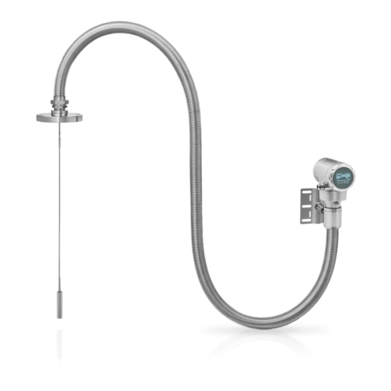
Do a check of the packing list to make sure that you have all the elements given in the order. POWERFLEX 2200 C – Compact version Figure 2-1: Scope of delivery (POWERFLEX 2200 C – Compact version) 1 Device (compact version: signal converter and probe) 2 Quick Start 3 DVD-ROM. - Page 7 INSTALLATION POWERFLEX 2200 C/F/S/D POWERFLEX 2200 S – Compact version with sensor extension Figure 2-2: Scope of delivery (POWERFLEX 2200 S – Compact version with sensor extension) 1 Signal converter 2 Sensor extension: Coaxial cable and support with one attached length of flexible stainless steel jacket...
- Page 8 INSTALLATION POWERFLEX 2200 C/F/S/D POWERFLEX 2200 F – Remote version Figure 2-3: Scope of delivery (POWERFLEX 2200 F – Remote version) 1 Signal converter 2 Quick Start 3 DVD-ROM. This contains the handbook, the quick start, the technical data sheet and related software.
- Page 9 INSTALLATION POWERFLEX 2200 C/F/S/D POWERFLEX 2200 D – Remote version with sensor extension Figure 2-4: Scope of delivery (POWERFLEX 2200 D – Remote version with sensor extension) 1 Signal converter 2 Quick Start 3 DVD-ROM. This contains the handbook, the quick start, the technical data sheet and related software.
-
Page 10: Visual Check
INSTALLATION POWERFLEX 2200 C/F/S/D 2.3 Visual Check INFORMATION! Inspect the packaging carefully for damages or signs of rough handling. Report damage to the carrier and to the local office of the manufacturer. Figure 2-5: Visual check 1 Device nameplate (for more data, refer to the handbook) 2 Process connection data (size and pressure rating, material reference and heat number) 3 Gasket material data –... -
Page 11: Transport
INSTALLATION POWERFLEX 2200 C/F/S/D 2.5 Transport Figure 2-7: How to hold the device: general data Figure 2-8: How to hold the device: cable data 1 Do not wind the cable probes less than 400 mm / 16¨ in diameter. 2 Do not hold the probe when you lift the device. -
Page 12: How To Prepare The Tank Before You Install The Device
INSTALLATION POWERFLEX 2200 C/F/S/D 2.7 How to prepare the tank before you install the device CAUTION! To avoid measuring errors and device malfunction, obey these precautions. 2.7.1 Pressure and temperature ranges Figure 2-9: Pressure and temperature ranges 1 Temperature at the process connection The temperature at the process connection must stay in the temperature range of the gasket material unless the de- vice is a High-Temperature version. - Page 13 INSTALLATION POWERFLEX 2200 C/F/S/D Ambient temperature / flange temperature, flange and threaded connection, in °C Figure 2-10: Ambient temperature / flange temperature, flange and threaded connection, in °C Ambient temperature / flange temperature, flange and threaded connection, in °F Figure 2-11: Ambient temperature / flange temperature, flange and threaded connection, in °F 1 Maximum ambient temperature, °C...
-
Page 14: General Information For Nozzles
INSTALLATION POWERFLEX 2200 C/F/S/D 2.7.2 General information for nozzles CAUTION! Follow these recommendations to make sure that the device measures correctly. They have an effect on the performance of the device. CAUTION! Do not put the process connection near to the product inlet. If the product that enters the tank touches the probe, the device will measure incorrectly. - Page 15 INSTALLATION POWERFLEX 2200 C/F/S/D For single cable and single rod probes: Figure 2-14: Recommended nozzle dimensions for single rod and single cable probes 1 Recommended conditions: h ≤ d, where h is the height of the tank nozzle and d is the diameter of the tank nozzle.
-
Page 16: Installation Requirements For Concrete Roofs
INSTALLATION POWERFLEX 2200 C/F/S/D CAUTION! Install coaxial probes in clean liquids that are not too viscous. 2.7.3 Installation requirements for concrete roofs Figure 2-17: Installation on a concrete roof 1 The diameter, d, of the hole must be greater than the thickness, t, of the concrete. -
Page 17: Installation In Standpipes (Stilling Wells And Bypass Chambers)
INSTALLATION POWERFLEX 2200 C/F/S/D Clearance between the probe and other objects in the tank Probe type Empty space (radius, R ), around the probe [mm] [inches] Coaxial Double rod / cable Single rod / cable 2.8.2 Installation in standpipes (stilling wells and bypass chambers) Use a standpipe if: •... -
Page 18: How To Install The Device On The Tank
INSTALLATION POWERFLEX 2200 C/F/S/D 2.9 How to install the device on the tank 2.9.1 How to install a device with a flange connection Equipment needed: • Device • Gasket (not supplied) • Wrench (not supplied) Figure 2-20: Flange connection • Make sure that the flange on the nozzle is level. -
Page 19: How To Install A Device With A Threaded Connection
INSTALLATION POWERFLEX 2200 C/F/S/D 2.9.2 How to install a device with a threaded connection Equipment needed: • Device • Gasket (not supplied) • 50 mm / 2¨ wrench (not supplied) Figure 2-21: Threaded connection • Make sure the tank connection is level. -
Page 20: How To Install A Cable Probe In The Tank
INSTALLATION POWERFLEX 2200 C/F/S/D 2.9.3 How to install a cable probe in the tank Figure 2-22: Wind cable probes carefully 1 Do not wind cable probes less than 400 mm / 16¨ in diameter. WARNING! If you bend the probe too much, you will damage the device and it will not measure accurately. -
Page 21: How To Turn Or Remove The Signal Converter
INSTALLATION POWERFLEX 2200 C/F/S/D 2.9.4 How to turn or remove the signal converter The converter turns 360°. The converter can be removed from the process connection assembly under process conditions. Figure 2-24: How to turn or remove the signal converter... -
Page 22: Recommendations For Pits And Tanks Made Of Non-Conductive Materials
INSTALLATION POWERFLEX 2200 C/F/S/D 2.9.5 Recommendations for pits and tanks made of non-conductive materials If you have a device with a single rod or a single cable probe and a thread connection, obey these instructions: • Put a metal sheet between the device and the process connection. -
Page 23: How To Attach The Weather Protection To The Device
INSTALLATION POWERFLEX 2200 C/F/S/D 2.9.6 How to attach the weather protection to the device The device and the weather protection option are supplied disassembled in the same box. The weather protection can also be supplied as an accessory. You must attach the weather protection when you install the device. - Page 24 INSTALLATION POWERFLEX 2200 C/F/S/D Figure 2-27: Installation of the weather protection on a vertical signal converter 1 Put the weather protection clamp around the top of the device. 2 Attach the two locking nuts to the threads on the weather protection clamp. Tighten the lock- ing nuts with a 10 mm socket wrench.
- Page 25 INSTALLATION POWERFLEX 2200 C/F/S/D Figure 2-28: Installation of the weather protection on a horizontal signal converter 1 Put the weather protection clamp around the front of the device (the end of the device that is nearest to the cable entry).
-
Page 26: How To Open The Weather Protection
INSTALLATION POWERFLEX 2200 C/F/S/D 2.9.7 How to open the weather protection Figure 2-29: How to open the weather protection 1 Remove the R-clip from the hole at the front of the weather protection cover. 2 Remove the weather protection cover. -
Page 27: Electromagnetic Compatibility
INSTALLATION POWERFLEX 2200 C/F/S/D 2.10 Electromagnetic compatibility The device design agrees with European Standard EN 61326-1 (2013) when installed in metallic tanks. The device design agrees with tests done according to performance criteria "A" of International Standards IEC 61000 (Parts 4-2, 4-4, 4-5, 4-6, 4-8, 4-9, 4-10, 4-12, and 4-16), and CISPR 11. -
Page 28: Electrical Connections
ELECTRICAL CONNECTIONS POWERFLEX 2200 C/F/S/D 3.1 Electrical installation: 2-wire, loop-powered 3.1.1 Compact version Terminals for electrical installation Figure 3-1: Terminals for electrical installation 1 Grounding terminal in the housing (if the electrical cable is shielded) 2 Current output - 3 Current output +... - Page 29 ELECTRICAL CONNECTIONS POWERFLEX 2200 C/F/S/D Figure 3-3: Procedure for electrical installation Equipment needed: • Small slotted tip screwdriver (not supplied) Procedure: 1 Do not disconnect the safety cord from the terminal compartment cover. Put the terminal compartment cover adjacent to the housing.
-
Page 30: Remote Version
ELECTRICAL CONNECTIONS POWERFLEX 2200 C/F/S/D 3.1.2 Remote version Terminals for electrical installation Figure 3-5: Terminals for electrical installation 1 Grounding terminal in the housing (if the electrical cable is shielded) 2 Current output - 3 Current output + 4 Location of the external grounding terminal (on the wall support) INFORMATION! Electrical power to the output terminal energizes the device. -
Page 31: Electrical Connection For Current Output
ELECTRICAL CONNECTIONS POWERFLEX 2200 C/F/S/D For more data about the signal cable between the remote converter and the probe housing, refer to the handbook. 3.2 Electrical connection for current output Figure 3-7: Electrical connections 1 Power supply 2 Optional junction box (ref. SJB 200W) for on-site readings of loop current 3 Optional connection to the grounding terminal 4 Output: 11.5...30 VDC for an output of 22 mA at the terminal... -
Page 32: Protection Category
ELECTRICAL CONNECTIONS POWERFLEX 2200 C/F/S/D 3.4 Protection category INFORMATION! The device fulfils all requirements per protection category IP66 / IP67. It also fulfils all requirements per NEMA type 4X (housing) and type 6P (probe). DANGER! Make sure that the cable gland is watertight. -
Page 33: Networks
ELECTRICAL CONNECTIONS POWERFLEX 2200 C/F/S/D 3.5 Networks 3.5.1 General information The device uses the HART® communication protocol. This protocol agrees with the HART® Communication Foundation standard. The device can be connected point-to-point. It can also have a polling address of 1 to 63 in a multi-drop network. -
Page 34: Multi-Drop Networks
ELECTRICAL CONNECTIONS POWERFLEX 2200 C/F/S/D 3.5.3 Multi-drop networks Figure 3-11: Multi-drop network 1 Address of the device (n+1 for multidrop networks) 2 Address of the device (1 for multidrop networks) 3 4 mA + HART® 4 Resistor for HART® communication 5 Power supply 6 HART®... -
Page 35: Operation
OPERATION POWERFLEX 2200 C/F/S/D 4.1 General notes For more data about device configuration, refer to the handbook. 4.2 Digital display screen 4.2.1 Local display screen layout Figure 4-1: Local display screen layout in Normal mode 1 Current output percentage (bar graph and text — only shown if the current output function is the same as the mea-... -
Page 36: Commissioning
OPERATION POWERFLEX 2200 C/F/S/D 4.3 Commissioning Use this procedure to change the probe length and give the top and bottom measuring limits. Values and parameters that can be changed are shown between « ... » in the illustrations that follow. Push the keypad buttons in the correct sequence: CAUTION! Make sure that you do this procedure before you use the device. - Page 37 OPERATION POWERFLEX 2200 C/F/S/D Screen Steps Description • [> > > > ] to change Scale 4 mA. Use this step to give the 4 mA output setting (0% limit) in the tank. Refer to the • [> > > > ] to change the position of the cursor.
- Page 38 OPERATION POWERFLEX 2200 C/F/S/D 4.4 Probe length calculation CAUTION! • Make sure that you do this procedure before you use the device. If you decrease the probe length, do the probe length calculation procedure before the • snapshot procedure. The probe length cannot be less than 600 mm / 23.6 for coaxial probes and 1000 mm / 39.4...
- Page 39 OPERATION POWERFLEX 2200 C/F/S/D Screen Steps Description The device measures the new probe length. If the display screen shows the error message "Failure! Pulse Lost" then speak to the supplier. • [> > > > ] for the selection of YES or [ ] for the The device shows the new probe length.
- Page 40 OPERATION POWERFLEX 2200 C/F/S/D 4.5 Snapshot The snapshot procedure is very important for the performance of the device. Make sure that the tank is empty or only filled to the minimum level before you do the procedure. Use this procedure (menu item 2.1.2) if there are objects adjacent to the probe that can cause parasitic signals.
- Page 41 OPERATION POWERFLEX 2200 C/F/S/D Screen Steps Description • [> > > > ], [ ] and [> > > > ] Push these buttons to start the snapshot procedure. • [> > > > ] for the selection of "Partially filled" or...
- Page 42 NOTES POWERFLEX 2200 C/F/S/D www.krohne.com 07/2016 - 4005318901 - QS POWERFLEX 2200 R01 en...
- Page 43 NOTES POWERFLEX 2200 C/F/S/D 07/2016 - 4005318901 - QS POWERFLEX 2200 R01 en www.krohne.com...
- Page 44 • Process Analysis • Services Head Office KROHNE Messtechnik GmbH Ludwig-Krohne-Str. 5 47058 Duisburg (Germany) Tel.: +49 203 301 0 Fax: +49 203 301 10389 info@krohne.com The current list of all KROHNE contacts and addresses can be found at: www.krohne.com...
Need help?
Do you have a question about the POWERFLEX 2200 C and is the answer not in the manual?
Questions and answers