KROHNE BW 25 Handbook
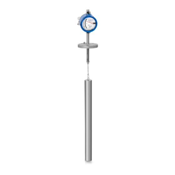
Displacer level transmitter for heavy-duty level or interface applications
Hide thumbs
Also See for BW 25:
- Handbook (72 pages) ,
- Handbook (56 pages) ,
- Supplementary instructions manual (24 pages)
Table of Contents
Advertisement
Quick Links
Download this manual
See also:
Handbook
Advertisement
Table of Contents

Related Manuals for KROHNE BW 25


Summary of Contents for KROHNE BW 25
- Page 1 BW 25 BW 25 BW 25 BW 25 Handbook Handbook Handbook Handbook Displacer Level Transmitter for heavy-duty level or interface applications © KROHNE 06/2015 - 4000432305 - MA BW25 R08 en...
- Page 2 All rights reserved. It is prohibited to reproduce this documentation, or any part thereof, without the prior written authorisation of KROHNE Messtechnik GmbH. Subject to change without notice. Copyright 2015 by KROHNE Messtechnik GmbH - Ludwig-Krohne-Str. 5 - 47058 Duisburg (Germany) www.krohne.com 06/2015 - 4000432305 - MA BW25 R08 en...
-
Page 3: Table Of Contents
4.3.2 Current output ESK4/ESK4A ....................25 4.4 Grounding ........................28 4.5 Protection category ......................29 5 Start-up 5.1 Start-up........................... 30 6 Operation 6.1 ESK4/4A – Loop Check Mode ..................31 6.2 Operating elements indicator M40................. 32 06/2015 - 4000432305 - MA BW25 R08 en www.krohne.com... - Page 4 7.5.2 Form (for copying) to accompany a returned device............43 7.6 Disposal .......................... 43 8 Technical data 8.1 Operating principle......................44 8.2 Technical data......................... 45 8.3 Dimensions ........................49 9 Appendix 9.1 Order code ........................52 www.krohne.com 06/2015 - 4000432305 - MA BW25 R08 en...
-
Page 5: Safety Instructions
• EC directive 94/9 EC - ATEX directive • EMC Directive 89/336/EC as well as • EN 61010 • EMC specification acc. to EN 61326/A1 • NAMUR recommendations NE 21 and NE 43 06/2015 - 4000432305 - MA BW25 R08 en www.krohne.com... -
Page 6: Safety Instructions From The Manufacturer
The manufacturer reserves the right to alter the content of its documents, including this disclaimer in any way, at any time, for any reason, without prior notification, and will not be liable in any way for possible consequences of such changes. www.krohne.com 06/2015 - 4000432305 - MA BW25 R08 en... -
Page 7: Product Liability And Warranty
This document is provided to help you establish operating conditions, which will permit safe and efficient use of this device. Special considerations and precautions are also described in the document, which appear in the form of icons as shown below. 06/2015 - 4000432305 - MA BW25 R08 en www.krohne.com... -
Page 8: Warnings And Symbols Used
In general, devices from the manufacturer may only be installed, commissioned, operated and maintained by properly trained and authorized personnel. This document is provided to help you establish operating conditions, which will permit safe and efficient use of this device. www.krohne.com 06/2015 - 4000432305 - MA BW25 R08 en... -
Page 9: Device Description
Figure 2-1: Scope of delivery 1 Measuring device (with options as specified in the customer order) 2 For indicator M40 – key 3 Handbook 4 Certificates and calibration report (as specified in the customer order) 06/2015 - 4000432305 - MA BW25 R08 en www.krohne.com... -
Page 10: Device Version
• Max. 2 limit switches • 2-wire current output 4…20 mA, HART® communication • PROFIBUS PA or FOUNDATION™ fieldbus • LCD display and digital outputs • Intrinsically safe (Ex i) or explosion-proof enclosure (Ex d) www.krohne.com 06/2015 - 4000432305 - MA BW25 R08 en... -
Page 11: Indicator Versions
K1 / K2 and ESK4/4A versions Figure 2-4: K1 / K2 and ESK4/4A versions 1 Indicator with K2 contact module 2 Indicator with ESK4/4A current output 4...20 mA Both versions can be combined with one another. 06/2015 - 4000432305 - MA BW25 R08 en www.krohne.com... - Page 12 DEVICE DESCRIPTION BW25 ESK4-FF / ESK4-PA fieldbus version Figure 2-5: ESK4-FF / ESK4-PA fieldbus version 1 Basic module with electronic magnet sensors 2 Connection bus module 3 Hardware settings www.krohne.com 06/2015 - 4000432305 - MA BW25 R08 en...
-
Page 13: Nameplate
4 Sizing data: temperature & pressure rating 5 PED data 6 Ex data 7 Electrical connection data 8 Note manual 9 KROHNE website Additional markings on the indicator • SO – sales order / item • PA – order • Vx – product configurator code •... -
Page 14: Installation
Align the gaskets. Tighten the nuts with the tightening torques of the appropriate pressure • rating. Do not lay signal cables directly next to cables for the power supply. • www.krohne.com 06/2015 - 4000432305 - MA BW25 R08 en... -
Page 15: Installation
4 and check for a tight fit. • Insert the displacer element and the spring suspension pin into the tank through the tank flange or into the preinstalled bypass chamber. • Tighten the flange connection. 06/2015 - 4000432305 - MA BW25 R08 en www.krohne.com... -
Page 16: Electrical Connections
INFORMATION! Look at the device nameplate to ensure that the device is delivered according to your order. Check for the correct supply voltage printed on the nameplate. www.krohne.com 06/2015 - 4000432305 - MA BW25 R08 en... -
Page 17: Electrical Connection Indicator M9
The connecting terminals have a pluggable design and can be removed in order to connect the lines. The built-in contact types are shown on the nameplate of the indicator. Electrical connection of the limit switches Contact Terminal no. Connection 2-wire NAMUR Connection 3-wire Connection Reed SPST 06/2015 - 4000432305 - MA BW25 R08 en www.krohne.com... - Page 18 • Slide the scale back to the latching point • Set contact pointers 1 and 2 to the desired switching point After setting has been carried out: Fix the contact pointers with the locking screw 3. www.krohne.com 06/2015 - 4000432305 - MA BW25 R08 en...
- Page 19 Current consumption in the position shown: Contact Type current ≤ 1 mA MIN 1 NAMUR ≤ 1 mA MIN 2 NAMUR ≥ 3 mA MAX 1 NAMUR ≥ 3 mA MAX 2 NAMUR 06/2015 - 4000432305 - MA BW25 R08 en www.krohne.com...
-
Page 20: Electrical Signal Output Esk2A
(4...20 mA). Exception: multidrop operation. In multidrop operation a maximum of 15 devices with HART® function can be operated in parallel, whereby their analogue outputs are switched inactive. (I approx. 4 mA per device). www.krohne.com 06/2015 - 4000432305 - MA BW25 R08 en... - Page 21 The ESK2A can be configured via HART® communication. DD (Device Description) as well as a DTM (Device Type Manager) are available for configuration (go to download centre at www.krohne.com). With the integrated HART® communication, the current level can be transmitted. Two limit values can be monitored.
-
Page 22: Electrical Connection Indicator M40
The connecting terminals have a pluggable design and can be removed in order to connect the cables. The built-in limit switch types are shown on the indicator. Electrical connection of the limit switches Contact Terminal no. Connection 2-wire NAMUR Connection 3-wire Connection Reed SPST www.krohne.com 06/2015 - 4000432305 - MA BW25 R08 en... - Page 23 • Slide the scale back to the latching point • Set contact pointers 1 and 2 to the desired switching point After setting has been carried out: Fix the contact pointers with the locking screw 3. 06/2015 - 4000432305 - MA BW25 R08 en www.krohne.com...
- Page 24 Current consumption in the position shown: Contact Type current ≤ 1 mA MIN 1 NAMUR ≤ 1 mA MIN 2 NAMUR ≥ 3 mA MAX 1 NAMUR ≥ 3 mA MAX 2 NAMUR www.krohne.com 06/2015 - 4000432305 - MA BW25 R08 en...
-
Page 25: Current Output Esk4/Esk4A
Figure 4-14: Electrical schematic for ESK2A with a protected extra-low voltage (PELV) circuit 1 Terminal connection 2 Converter supply isolator with electrical isolation 3 Power supply (see supply isolator information) 4 Measuring signal 4...20 mA 5 External load, HART® communication 06/2015 - 4000432305 - MA BW25 R08 en www.krohne.com... - Page 26 Use a twisted two-core cable to prevent electrical interference from impeding the DC output signal. In some cases a shielded cable may be necessary. The cable shield may only be earthed (grounded) at one place (on the power supply unit). www.krohne.com 06/2015 - 4000432305 - MA BW25 R08 en...
- Page 27 The ESK4/4A can be configured via HART® communication. DD (Device Description) and a DTM (Device Type Manager) are available for configuration (go to download center at www.krohne.com). The current flow rate can be transmitted using the integrated HART® communication. Two limit values can be monitored.
-
Page 28: Grounding
3 Grounding connection in the indicator M40 4 External grounding connection M40 DANGER! The grounding wire may not transfer any interference voltage. Do not use this grounding wire to ground any other electrical devices. www.krohne.com 06/2015 - 4000432305 - MA BW25 R08 en... -
Page 29: Protection Category
• The cable feedthroughs 2 must be tightened. • Close the unused cable feedthroughs using blanking plugs 1. Figure 4-16: How to make the installation agree with protection category IP65 (M9) or IP66/IP68 (M40) 06/2015 - 4000432305 - MA BW25 R08 en www.krohne.com... -
Page 30: Start-Up
(empty tank) the indicator shows "0" at an operating temperature of +20 ° Do not change the factory setting of the pointer. This applies in particular where high • pressures and high temperatures are involved. www.krohne.com 06/2015 - 4000432305 - MA BW25 R08 en... -
Page 31: Operation
• Exit loop check mode by holding down the microswitch (longer than 6 seconds). The current output jumps back to measuring mode 2. INFORMATION! If the microswitch has not been pressed for longer than 60 seconds, the ESK4 automatically reverts to measuring mode 2. 06/2015 - 4000432305 - MA BW25 R08 en www.krohne.com... -
Page 32: Operating Elements Indicator M40
The mechanical keys and keys for the bar magnet have the same functionality. In this documentation the keys are represented as symbols to describe the operating functions: Operation keys Button Symbol → right ↑ Enter www.krohne.com 06/2015 - 4000432305 - MA BW25 R08 en... -
Page 33: Basic Principles Of Operation
Main menu Sub-menu Function Edit ↑ ↑ ↑ → ↑ ^ ^ ^ ^ mode ^ ^ ^ ^ ^ ^ ^ ^ ^ ^ ^ ^ ^ ^ ^ ^ 06/2015 - 4000432305 - MA BW25 R08 en www.krohne.com... -
Page 34: Changing The Settings In The Menu
6.3.4 Measures in the event of faulty indications If the indications on the display or the responses to keypad commands are faulty, you have to do a hardware reset. Switch the power supply OFF and ON again. www.krohne.com 06/2015 - 4000432305 - MA BW25 R08 en... -
Page 35: Overview Of The Most Important Functions And Indicators
The value set is represented by a 20 mA analogue current output. If the current value exceeds the preset value, an alarm is indicated. Level units The following units are supported: m – cm – mm – inch – feet 06/2015 - 4000432305 - MA BW25 R08 en www.krohne.com... -
Page 36: Error Messages
Activate linearization or carry it out again LINEARIZED activated = measuring (HART® communication and linearization error software are required; the original calibration values must be known), or send the device back to the manufacturer for linearization. www.krohne.com 06/2015 - 4000432305 - MA BW25 R08 en... - Page 37 3.12), and is no longer coupled with the measured value. DDs ("driver") for HART® Tools, process control (e.g. Siemens PDM or AMS) PACTware™ and HART® DTMs are available at the KROHNE Download Center. 06/2015 - 4000432305 - MA BW25 R08 en www.krohne.com...
-
Page 38: Service
• Insert the contact module into the third slot of the bracket until the semi-circle 3 surrounds the pointer cylinder. Figure 7-1: Retrofitting the limit switch module The contact module connecting terminals feature a pluggable design and can be removed in order to connect the cables. www.krohne.com 06/2015 - 4000432305 - MA BW25 R08 en... - Page 39 • Device address • Serial number • Measuring point designation • Digital measured value query in level units, % and mA • Test / setting functions • Calibration 4.00 and 20.00 mA 06/2015 - 4000432305 - MA BW25 R08 en www.krohne.com...
-
Page 40: Indicator M40
The ESK4/4A is calibrated at the factory, making it possible to replace it or retrofit it without recalibrating. • De-energise the ESK4/4A. • Lift and remove the ESK4/4A with a screwdriver. www.krohne.com 06/2015 - 4000432305 - MA BW25 R08 en... - Page 41 • Measuring point designation • Digital measured value query in level units, % and mA • Test / setting functions • Calibration 4.00 and 20.00 mA • Set current output to any desired value 06/2015 - 4000432305 - MA BW25 R08 en www.krohne.com...
-
Page 42: Spare Parts Availability
• such dangerous substances, to enclose a certificate with the device confirming that is safe to handle and stating the • product used. www.krohne.com 06/2015 - 4000432305 - MA BW25 R08 en... -
Page 43: Form (For Copying) To Accompany A Returned Device
We hereby confirm that there is no risk to persons or the environment through any residual media contained in the device when it is returned. Date: Signature: Stamp: 7.6 Disposal CAUTION! Disposal must be carried out in accordance with legislation applicable in your country. 06/2015 - 4000432305 - MA BW25 R08 en www.krohne.com... -
Page 44: Technical Data
Due to the length of the spring suspension pin 3, the unmeasureable area is L = 340 mm. Figure 8-1: Operating principle 1 Measuring spring 2 Measuring range 3 L ≥ 340 mm 4 Displacer rod www.krohne.com 06/2015 - 4000432305 - MA BW25 R08 en... -
Page 45: Technical Data
40 barg / 580 psig – optional to 400 barg / 5802 psig Max. operating pressure Standard flange DN50 – PN40 / 2¨ ASME 300 lb Optional flange ...DN100...PN400 / …4¨ ASME ...2500 lb 06/2015 - 4000432305 - MA BW25 R08 en www.krohne.com... - Page 46 3...7 mm 0.118...0.276¨ M20 × 1.5 8...13 mm 0.315...0.512¨ M16 × 1.5 Nickel-plated brass 5...9 mm 0.197...0.355¨ M20 × 1.5 Nickel-plated brass 10...14 mm 0.394...0.552¨ 1 M9 2 M9 and M40 www.krohne.com 06/2015 - 4000432305 - MA BW25 R08 en...
- Page 47 650 ohms (30 VDC) Min. load for HART® 250 ohms ESK2A / ESK4/4A Manufacturer name (code) KROHNE Messtechnik (69 = 0x45) Model name ESK2A (226 = 0xE2) HART 5 ESK4 (214 = 0xD6) HART 5 ESK4 (17854 = 0x45BE) HART 5...
- Page 48 IEC 61158-2 and FISCO model Communication standard Profibus PA profile 3.02 PNO ID 4531 HEX Power supply Bus supply Nominal current 16 mA Error current 23 mA Starting current after 10 ms < Nominal current www.krohne.com 06/2015 - 4000432305 - MA BW25 R08 en...
-
Page 49: Dimensions
≥ 20 [mm] min. 340 ≥ 0.79 ["] 7.13 4.33 5.44 6.62 min 13.39 4.18 11.94 7.29 1 Length of the displacer rod (measuring area) 2 According to the operating conditions 06/2015 - 4000432305 - MA BW25 R08 en www.krohne.com... - Page 50 ≥ 20 [mm] min. 340 ≥ 0.79 ["] 5.44 3.70 5.44 6.62 min 13.39 4.49 11.94 7.76 1 Length of the displacer rod (measuring area) 2 According to the operating conditions www.krohne.com 06/2015 - 4000432305 - MA BW25 R08 en...
- Page 51 Dimensions of bypass chamber Bypass chamber Dimensions of bypass chamber [mm] ["] 13.4 1 Connection according to DIN EN 1092-1 2 Length of the displacer rod (measuring area) 3 Connection according to ASME B16.5 06/2015 - 4000432305 - MA BW25 R08 en www.krohne.com...
-
Page 52: Appendix
VG55 4 Liquid level indicator BW 25 with displacer / local indication, max. measuring range: 6 m / 19.68 ft Liquid level indicator BW 25 with displacer / local indication, max. measuring range: 6 m / 19.68 ft Liquid level indicator BW 25 with displacer / local indication, max. - Page 53 Order code (complete this code on the pages that follow) VG55 VG55 Order code (complete this code on the pages that follow) Order code (complete this code on the pages that follow) 06/2015 - 4000432305 - MA BW25 R08 en www.krohne.com...
- Page 54 Order code (complete this code on the pages that follow) VG55 VG55 Order code (complete this code on the pages that follow) Order code (complete this code on the pages that follow) www.krohne.com 06/2015 - 4000432305 - MA BW25 R08 en...
- Page 55 F 3.1 on pressure boundary parts and PMI test pressure boundary parts + 3.1 H 3.1 on pressure boundary parts. Data are archived for 10 years by KROHNE. Includes PMI test pressure boundary parts + 3.1. Dye penetrant certificate (EN 571-1)
- Page 56 • Process Analysis • Services Head Office KROHNE Messtechnik GmbH Ludwig-Krohne-Str. 5 47058 Duisburg (Germany) Tel.: +49 203 301 0 Fax: +49 203 301 10389 info@krohne.com The current list of all KROHNE contacts and addresses can be found at: www.krohne.com...
Need help?
Do you have a question about the BW 25 and is the answer not in the manual?
Questions and answers