
Related Manuals for KROHNE LT40 C


Summary of Contents for KROHNE LT40 C
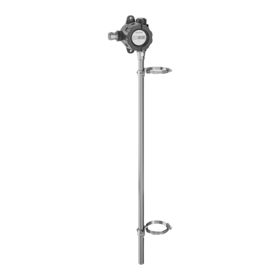
- Page 1 LT40 C/F Supplementary Instructions Reed-chain level transmitter for the BM26A series bypass level indicator Supplementary Instructions for UKEX applications © KROHNE 10/2021 - 4009051601 - AD UKEX LT40 R01 en...
-
Page 2: Table Of Contents
2.2 Operating conditions ......................9 2.2.1 General notes.......................... 9 2.2.2 Ambient and service temperatures ..................9 2.2.3 Ambient and process temperatures..................9 2.2.4 Compact version (LT40 C) ..................... 10 2.2.5 Remote version (LT40 F) ....................... 14 3 Electrical connections 3.1 General notes ......................... 19 3.2 Terminal compartment .................... - Page 3 CONTENTS LT40 C/F 5.4 How to remove the device ....................26 5.4.1 General notes........................26 5.4.2 Replacement of ER transmitter.................... 26 5.4.3 Replacement of the first version of the LT40 ............... 26 5.4.4 Replacement of the LT40 ...................... 27 5.5 Manufacturer ........................27 5.6 Returning the device to the manufacturer..............
-
Page 4: General Safety Information
GENERAL SAFETY INFORMATION LT40 C/F 1.1 Scope of the document These instructions are applicable only to the explosion-protection version of the LT40 reed-chain level transmitter. For all other data, use the Quick Start and Handbook. If you do not have these documents, please contact the nearest sales office or download them from the manufacturer's website. -
Page 5: Device Categories
GENERAL SAFETY INFORMATION LT40 C/F 1.4 Device categories 1.4.1 Ex ia-approved devices The Ex ia-approved device has the marking that follows: • II 1 G Ex ia IIC T6...T1 Ga or II 2 G Ex ia IIC T6...T1 Gb The Ex ia-approved device is suitable for use in potentially explosive atmospheres of all flammable substances in Gas Groups IIA, IIB and IIC. -
Page 6: Nameplate
GENERAL SAFETY INFORMATION LT40 C/F 1.5 Nameplate Figure 1-1: Nameplate for the reed-chain level transmitter 1 Certificate number 2 Type of device protection for explosive gas atmospheres 3 Ex ia approval: Intrinsically safe circuit data. Refer to ⑥ for the input voltage range. -
Page 7: Installation
INSTALLATION LT40 C/F 2.1 Precautions 2.1.1 General notes WARNING! When you install the device, obey the conditions in the UK-Type Examination certificate. These conditions include: • The special conditions for safe use. • The Essential Safety Requirements. You can download the certificate from our website. -
Page 8: Electrostatic Discharge
INSTALLATION LT40 C/F 2.1.3 Electrostatic discharge DANGER! Risk of electrostatic discharge from the label and painted surfaces. Do not install in a location where the electrostatic charge can increase. For example: • locations near ventilation systems, • locations where there is a risk of an increase in electrostatic charge caused by compressed air and dust, •... -
Page 9: Operating Conditions
Version Approval Ambient Service temperature range temperature Converter Reed chain range [°C] LT40 C or LT40 F Ex ia -40...+80 -40...+85 LT40 C Ex db -40...+80 -40...+85 LT40 F -40...+85 -60...+85 2.2.3 Ambient and process temperatures... -
Page 10: Compact Version (Lt40 C)
Make sure that the service temperature of the reed-chain level transmitter is in the permitted limits. For more data, refer to Ambient and service temperatures on page 9 . 2.2.4 Compact version (LT40 C) 4...20 mA and 4...20 mA / HART... - Page 11 INSTALLATION LT40 C/F 4...20 mA and 4...20 mA / HART Maximum limits for measuring chamber with EPL Gb Temperature Maximum process Maximum ambient temperature class temperature Without insulation With insulation [°C] +110 +120 +130 +150 +175 +195 +210 +250 +290...
- Page 12 INSTALLATION LT40 C/F PROFIBUS PA / FOUNDATION™ fieldbus Maximum limits for measuring chamber with EPL Ga/Gb Temperature Maximum Maximum ambient temperature class process FISCO system Barrier (Po ≤ 0.84 W) temperature Without With Without With insulation insulation insulation insulation [°C]...
- Page 13 If the process temperature is less than -40°C, then make sure that the ambient temperature and the service temperature for the LT40 C reed-chain level transmitter are more than the minimum permitted values. For more data, refer to Ambient and service temperatures on page 9.
-
Page 14: Remote Version (Lt40 F)
INSTALLATION LT40 C/F 2.2.5 Remote version (LT40 F) WARNING! Do not attach the remote converter housing of the LT40 F reed-chain level transmitter to the BM26A series bypass level indicator. 4...20 mA and 4...20 mA / HART Maximum limits for measuring chamber with EPL Ga/Gb... - Page 15 INSTALLATION LT40 C/F 4...20 mA and 4...20 mA / HART Maximum limits for measuring chamber with EPL Gb Temperature Maximum process Maximum ambient temperature class temperature Without insulation With insulation [°C] +110 +120 +130 +150 +175 +195 +210 +250 +290...
- Page 16 INSTALLATION LT40 C/F PROFIBUS PA / FOUNDATION™ fieldbus Maximum limits for measuring chamber with EPL Ga/Gb Temperature Maximum Maximum ambient temperature class process Ex ia IIC temperature FISCO system Barrier (Po ≤ 0.84 W) Without With Without With insulation insulation...
- Page 17 INSTALLATION LT40 C/F PROFIBUS PA / FOUNDATION™ fieldbus Maximum limits for measuring chamber with EPL Gb Temperatu Maximum Maximum ambient temperature re class process Ex ia IIC Ex ib IIC temperature Barrier FISCO system Barrier (Po ≤ 0.84 W) (Po ≤ 5.32 W) and...
- Page 18 INSTALLATION LT40 C/F Minimum limits (Ex ia version) Minimum process Minimum ambient temperature temperature Without insulation With insulation [°C] If the process temperature is less than -40°C, then make sure that the ambient temperature and the service temperature for the LT40 F reed-chain level transmitter are more than the minimum permitted values.
-
Page 19: Electrical Connections
ELECTRICAL CONNECTIONS LT40 C/F 3.1 General notes WARNING! • De-energize the circuit when you do work on the device. • Do not blow dust with compressed air if it collects on the housing. Clean the device with a damp cloth before you remove the terminal compartment cover. -
Page 20: How To Close The Terminal Compartment
ELECTRICAL CONNECTIONS LT40 C/F 3.2.2 How to close the terminal compartment Equipment needed • 4-mm Allen wrench (not supplied) Figure 3-2: How to close the terminal compartment cover • Put the LCD display module (or the dummy display module - if the LT40 has this component) on the housing. -
Page 21: Equipotential Bonding System
ELECTRICAL CONNECTIONS LT40 C/F 3.4 Equipotential bonding system Connect the device to the equipotential bonding system for the hazardous location. You can use the external ground terminal or the internal ground connection of the housing to connect the device to the equipotential bonding system. -
Page 22: Ex I Version Of The Reed-Chain Level Transmitter
ELECTRICAL CONNECTIONS LT40 C/F 3.5 Ex i version of the reed-chain level transmitter 3.5.1 How to connect the electrical cables Refer to the handbook for data about the device terminals. Obey the instructions that follow: • Use the electrical connection procedure in the handbook. -
Page 23: Ex D Version Of The Reed-Chain Level Transmitter
ELECTRICAL CONNECTIONS LT40 C/F 3.6 Ex d version of the reed-chain level transmitter 3.6.1 How to connect the electrical cables Terminal compartment • If you connect electrical wires to the terminals in the flameproof compartment, use approved flameproof cable glands (M20×1.5 or ½ NPT). The cable gland must have an UK-Type Examination Certificate that agrees with EN 60079-1. -
Page 24: Start-Up
START-UP LT40 C/F WARNING! Make sure that it is safe to supply electrical power. Do a start-up check: • Does the information given on the nameplate agree with the application? Does the service temperature of the cable gland and the electrical cable agree with the service temperature of the reed-chain level transmitter? •... -
Page 25: Service
SERVICE LT40 C/F 5.1 Periodic maintenance In normal operational conditions, no maintenance is necessary. If it is necessary, maintenance must be done by approved personnel (the manufacturer or personnel approved by the manufacturer). INFORMATION! For maintenance and inspection of electrical installations, refer to EN 60079-17. -
Page 26: How To Remove The Device
SERVICE LT40 C/F 5.4 How to remove the device 5.4.1 General notes DANGER! If the device is installed in a potentially explosive atmosphere and energized, obey the instructions that follow: • De-energize the device. • Disconnect the electrical wires. • Make sure that all electrical wires are isolated from the ground. -
Page 27: Replacement Of The Lt40
SERVICE LT40 C/F 5.4.4 Replacement of the LT40 If you must replace the LT40 reed-chain level transmitter that agrees with UK-Type Examination Certificate CSAE 21UKEX1531X, send an order for the device with the applicable Ex approval. Record the serial number of the reed chain level transmitter that you will replace and send this data to your supplier. -
Page 28: Form (For Copying) To Accompany A Returned Device
SERVICE LT40 C/F 5.6.2 Form (for copying) to accompany a returned device CAUTION! To avoid any risk for our service personnel, this form has to be accessible from outside of the packaging with the returned device. Company: Address: Department: Name:... - Page 29 NOTES LT40 C/F 10/2021 - 4009051601 - AD UKEX LT40 R01 en www.krohne.com...
- Page 30 NOTES LT40 C/F www.krohne.com 10/2021 - 4009051601 - AD UKEX LT40 R01 en...
- Page 31 NOTES LT40 C/F 10/2021 - 4009051601 - AD UKEX LT40 R01 en www.krohne.com...
- Page 32 Engineering, commissioning, calibration, maintenance and training services Head Office KROHNE Messtechnik GmbH Ludwig-Krohne-Str. 5 47058 Duisburg (Germany) Tel.: +49 203 301 0 Fax: +49 203 301 10389 info@krohne.de The current list of all KROHNE contacts and addresses can be found at: www.krohne.com...
Need help?
Do you have a question about the LT40 C and is the answer not in the manual?
Questions and answers