Sign In
Upload
Manuals
Brands
KROHNE Manuals
Transmitter
POWERFLEX 2200 C
KROHNE POWERFLEX 2200 C Manuals
Manuals and User Guides for KROHNE POWERFLEX 2200 C. We have
2
KROHNE POWERFLEX 2200 C manuals available for free PDF download: Manual, Quick Start Manual
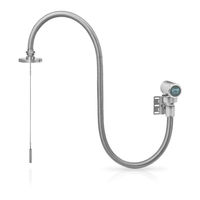
KROHNE POWERFLEX 2200 C Manual (140 pages)
Guided Radar (TDR) Level Transmitter for the nuclear industry
Brand:
KROHNE
| Category:
Transmitter
| Size: 4.83 MB
Table of Contents
Table of Contents
3
1 Safety Instructions
7
Software History
7
Intended Use
7
Certification
7
Electromagnetic Compatibility
8
Safety Instructions from the Manufacturer
9
Copyright and Data Protection
9
Disclaimer
9
Product Liability and Warranty
10
Information Concerning the Documentation
10
Warnings and Symbols Used
11
Safety Instructions for the Operator
11
2 Device Description
12
Scope of Delivery
12
Device Description
16
Visual Check
18
Nameplates
19
Nameplate
19
3 Installation
21
General Notes on Installation
21
Storage
21
Transport
22
Pre-Installation Requirements
22
How to Prepare the Tank before You Install the Device
23
Pressure and Temperature Ranges
23
General Information for Nozzles
24
Installation Requirements for Concrete Roofs
27
Installation Recommendations for Liquids
27
General Requirements
27
How to Attach Probes to the Bottom of the Tank
28
Installation in Standpipes (Stilling Wells and Bypass Chambers)
31
How to Install the Device on the Tank: General Notes
32
How to Install a Device with a Flange Connection
32
How to Install a Device with a Threaded Connection
33
How to Install a Cable Probe in the Tank
34
Recommendations for Pits and Tanks Made of Non-Conductive Materials
35
How to Turn or Remove the Signal Converter
36
How to Attach the Weather Protection to the Device
37
How to Open the Weather Protection
40
How to Install the Device on the Tank: Remote Version
41
Wall Support for the Remote Version
41
How to Prepare the Sensor Extension for Installation
41
4 Electrical Connections
46
Safety Instructions
46
Electrical Installation: 2-Wire, Loop-Powered
46
Compact Version
46
Remote Version
48
Remote Device Data
49
Requirements for Signal Cables Supplied by the Customer
49
How to Prepare a Signal Cable Supplied by the Customer
50
How to Connect the Signal Cable to the Device
51
Electrical Connection for Current Output
55
Protection Category
55
Networks
56
General Information
56
Point-To-Point Networks
56
Multi-Drop Networks
57
5 Start-Up
58
How to Start the Device
58
Start-Up Checklist
58
Operating Concept
58
Digital Display Screen
59
Local Display Screen Layout
59
Functions of Keypad Buttons
60
Remote Communication with Pactware
61
Remote Communication with the AMS™ Device Manager
62
6 Operation
63
User Modes
63
Normal Mode
63
Configuration Mode
64
General Notes
64
How to Get Access to the Commissioning Menu
65
Menu Overview
66
Keypad Functions
67
Function Description
70
Further Information on Device Configuration
77
Commissioning
77
Probe Length Calculation
79
Snapshot
80
Test
82
Protection of the Device Settings
83
HART® Network Configuration
84
Distance Measurement
85
Level Measurement
85
How to Configure the Device to Measure Volume or Mass
86
Thresholds and Parasitic Signals
88
How to Decrease the Length of Probes
90
Status and Error Messages
92
Device Status (Markers)
92
Error Handling
94
7 Service
100
Periodic Maintenance
100
Keep the Device Clean
100
How to Replace Device Components
100
Service Warranty
100
Availability of Services
101
Returning the Device to the Manufacturer
101
General Information
101
Form (for Copying) to Accompany a Returned Device
102
Disposal
103
8 Technical Data
104
Measuring Principle
104
Probe Options
107
Process Connections
108
Minimum Power Supply Voltage
109
Measurement Limits
110
Dimensions and Weights
116
9 Description of HART Interface
125
General Description
125
Software Description
125
Connection Variants
126
Point-To-Point Connection - Analogue / Digital Mode
126
Multi-Drop Connection (2-Wire Connection)
126
HART® Device Variables
126
Field Communicator 375/475 (FC 375/475)
127
Installation
127
Operation
127
Asset Management Solutions (AMS ® )
128
Installation
128
Operation
128
Parameter for the Basic Configuration
128
Field Device Tool / Device Type Manager (FDT / DTM)
128
Process Device Manager (PDM)
129
Installation
129
Operation
129
HART ® Menu Tree for Basic-DD
130
Overview Basic-DD Menu Tree (Positions in Menu Tree)
130
Basic-DD Menu Tree (Details for Settings)
130
HART ® Menu Tree for AMS
132
Overview AMS Menu Tree (Positions in Menu Tree)
132
AMS Menu Tree (Details for Settings)
132
HART® Menu Tree for PDM
134
Overview PDM Menu Tree (Positions in Menu Tree)
134
PDM Menu Tree (Details for Settings)
135
Status Bar
136
10 Appendix
137
Glossary
137
Advertisement
KROHNE POWERFLEX 2200 C Quick Start Manual (44 pages)
Guided Radar (TDR) Level Transmitter for the nuclear industry
Brand:
KROHNE
| Category:
Laser Level
| Size: 2.29 MB
Table of Contents
Table of Contents
2
1 Safety Instructions
4
2 Installation
5
Intended Use
5
Scope of Delivery
6
Visual Check
10
Storage
10
Transport
11
Pre-Installation Requirements
11
How to Prepare the Tank before You Install the Device
12
Pressure and Temperature Ranges
12
General Information for Nozzles
14
Installation Requirements for Concrete Roofs
16
Installation Recommendations for Liquids
16
General Requirements
16
Installation in Standpipes (Stilling Wells and Bypass Chambers)
17
How to Install the Device on the Tank
18
How to Install a Device with a Flange Connection
18
How to Install a Device with a Threaded Connection
19
How to Install a Cable Probe in the Tank
20
How to Turn or Remove the Signal Converter
21
Recommendations for Pits and Tanks Made of Non-Conductive Materials
22
How to Attach the Weather Protection to the Device
23
How to Open the Weather Protection
26
Electromagnetic Compatibility
27
3 Electrical Connections
28
Electrical Installation: 2-Wire, Loop-Powered
28
Compact Version
28
Remote Version
30
Electrical Connection for Current Output
31
Minimum Power Supply Voltage
31
Protection Category
32
Networks
33
General Information
33
Point-To-Point Networks
33
Multi-Drop Networks
34
4 Operation
35
General Notes
35
Digital Display Screen
35
Local Display Screen Layout
35
Functions of Keypad Buttons
35
Commissioning
36
Advertisement
Related Products
KROHNE POWERFLEX 2200 S
KROHNE POWERFLEX 2200 F
KROHNE POWERFLEX 2200 D
KROHNE OPTIFLEX 2200
KROHNE OPTIFLEX 2200 C/F
KROHNE SMARTMAC 200 W
KROHNE OPTISWIRL 2100
KROHNE OPTIFLUX 2070
KROHNE OPTIMASS 2010C
KROHNE 2000 Series
KROHNE Categories
Measuring Instruments
Transmitter
Accessories
Switch
Media Converter
More KROHNE Manuals
Login
Sign In
OR
Sign in with Facebook
Sign in with Google
Upload manual
Upload from disk
Upload from URL