KROHNE OPTIWAVE 5400 C Handbook
24 ghz radar (fmcw) level transmitter for liquids in basic process applications
Hide thumbs
Also See for OPTIWAVE 5400 C:
- Supplementary instructions manual (36 pages) ,
- Supplementary instructions manual (32 pages) ,
- Supplementary instructions manual (32 pages)
Table of Contents

Subscribe to Our Youtube Channel
Related Manuals for KROHNE OPTIWAVE 5400 C


Summary of Contents for KROHNE OPTIWAVE 5400 C
- Page 1 OPTIWAVE 5400 C OPTIWAVE 5400 C OPTIWAVE 5400 C OPTIWAVE 5400 C Handbook Handbook Handbook Handbook 24 GHz Radar (FMCW) Level Transmitter for liquids in basic process applications © KROHNE 01/2021 - 4005813703 - MA OPTIWAVE 5400 R03b en...
- Page 2 All rights reserved. It is prohibited to reproduce this documentation, or any part thereof, without the prior written authorisation of KROHNE Messtechnik GmbH. Subject to change without notice. Copyright 2021 by KROHNE Messtechnik GmbH - Ludwig-Krohne-Str. 5 - 47058 Duisburg (Germany) www.krohne.com 01/2021 - 4005813703 - MA OPTIWAVE 5400 R03b en...
-
Page 3: Table Of Contents
CONTENTS OPTIWAVE 5400 C 1 Safety instructions 1.1 Software history ....................... 7 1.2 Intended use ........................8 1.3 Certification ........................8 1.4 Radio approvals ........................ 9 1.4.1 European Union (EU)....................... 9 1.4.2 U.S.A. and Canada......................... 12 1.5 Safety instructions from the manufacturer ..............15 1.5.1 Copyright and data protection .................... - Page 4 CONTENTS OPTIWAVE 5400 C 4 Electrical connections 4.1 Safety instructions......................48 4.2 General notes ......................... 48 4.3 Electrical installation: output options with cable gland ..........49 4.4 Electrical installation: output options with an M12 male connector......53 4.5 Electrical connection for current output ............... 53 4.5.1 Non-Ex devices ........................
- Page 5 CONTENTS OPTIWAVE 5400 C 7 Service 7.1 Periodic maintenance....................122 7.1.1 General notes........................122 7.1.2 Maintenance of the O-rings for the housing covers............122 7.1.3 How to clean the top surface of the device................. 123 7.1.4 How to clean horn antennas under process conditions............. 123 7.2 Service warranty......................
- Page 6 CONTENTS OPTIWAVE 5400 C 9.9 HART® menu tree for AMS..................164 9.9.1 Overview AMS menu tree (positions in menu tree) ............164 9.9.2 AMS menu tree (details for settings).................. 165 9.10 HART® menu tree for PDM..................168 9.10.1 Overview PDM menu tree (positions in menu tree)............168 9.10.2 PDM menu tree (details for settings) ................
-
Page 7: Safety Instructions
SAFETY INSTRUCTIONS OPTIWAVE 5400 C 1.1 Software history "Firmware revision" agrees with NAMUR NE 53. It is a series of numbers used to record the revision status of embedded software (firmware) in electronic equipment assemblies. It gives data on the type of changes made and the effect that changes have on compatibility. -
Page 8: Intended Use
SAFETY INSTRUCTIONS OPTIWAVE 5400 C 1.2 Intended use CAUTION! Responsibility for the use of the measuring devices with regard to suitability, intended use and corrosion resistance of the used materials against the measured fluid lies solely with the operator. INFORMATION! The manufacturer is not liable for any damage resulting from improper use or use for other than the intended purpose. -
Page 9: Radio Approvals
SAFETY INSTRUCTIONS OPTIWAVE 5400 C 1.4 Radio approvals 1.4.1 European Union (EU) INFORMATION! LPR (Level Probing Radar) LPR (Level Probing Radar) LPR (Level Probing Radar) LPR (Level Probing Radar) devices measure level in the open air or in a closed space (a metallic tank etc.). - Page 10 SAFETY INSTRUCTIONS OPTIWAVE 5400 C S/N: xxxxxxxxxxxxxxxxxxx Manufacturing date: YYYY-MM-DD Tag No: Figure 1-1: European Union: radio approval information on the nameplate 1 Type code (defined in order) 2 HVIN (Hardware Version Identification Number). This number gives the radar signal frequency (24GHZ = 24 GHz), the...
- Page 11 SAFETY INSTRUCTIONS OPTIWAVE 5400 C LPR (Level Probing Radar) devices only Use approved personnel to install the device. If the device is operated in the open air (outdoors), it agrees with the RED (Radio Equipment Directive) if you obey these instructions: •...
-
Page 12: And Canada
SAFETY INSTRUCTIONS OPTIWAVE 5400 C 1.4.2 U.S.A. and Canada INFORMATION! LPR (Level Probing Radar) LPR (Level Probing Radar) devices measure level in the open air or in a closed space (a metallic LPR (Level Probing Radar) LPR (Level Probing Radar) tank etc.). - Page 13 SAFETY INSTRUCTIONS OPTIWAVE 5400 C LEGAL NOTICE! IC IC IC IC This device complies with Industry Canada licence-exempt RSS standard(s). Operation is subject to the following conditions: 1. This device may not cause harmful interference, and 2. this device must accept any interference received, including interference that may cause un- desired operation.
- Page 14 SAFETY INSTRUCTIONS OPTIWAVE 5400 C S/N: xxxxxxxxxxxxxxxxxxx Manufacturing date: YYYY-MM-DD Tag No: Figure 1-2: U.S.A. and Canada: radio approval information on the nameplate 1 Type code (defined in order) 2 HVIN (Hardware Version Identification Number). This number gives the radar signal frequency (24GHZ = 24 GHz), the...
-
Page 15: Safety Instructions From The Manufacturer
SAFETY INSTRUCTIONS OPTIWAVE 5400 C 1.5 Safety instructions from the manufacturer 1.5.1 Copyright and data protection The contents of this document have been created with great care. Nevertheless, we provide no guarantee that the contents are correct, complete or up-to-date. -
Page 16: Product Liability And Warranty
SAFETY INSTRUCTIONS OPTIWAVE 5400 C 1.5.3 Product liability and warranty The operator shall bear responsibility for the suitability of the device for the specific purpose. The manufacturer accepts no liability for the consequences of misuse by the operator. Improper installation or operation of the devices (systems) will cause the warranty to be void. The respective "Standard Terms and Conditions"... -
Page 17: Warnings And Symbols Used
SAFETY INSTRUCTIONS OPTIWAVE 5400 C 1.5.5 Warnings and symbols used Safety warnings are indicated by the following symbols. DANGER! This warning refers to the immediate danger when working with electricity. DANGER! This warning refers to the immediate danger of burns caused by heat or hot surfaces. -
Page 18: Device Description
DEVICE DESCRIPTION OPTIWAVE 5400 C 2.1 Scope of delivery INFORMATION! Do a check of the packing list to make sure that you have all the elements given in the order. Figure 2-1: Scope of delivery 1 Signal converter, process connection and antenna in the ordered version 2 Antenna extensions (option). -
Page 19: Device Description
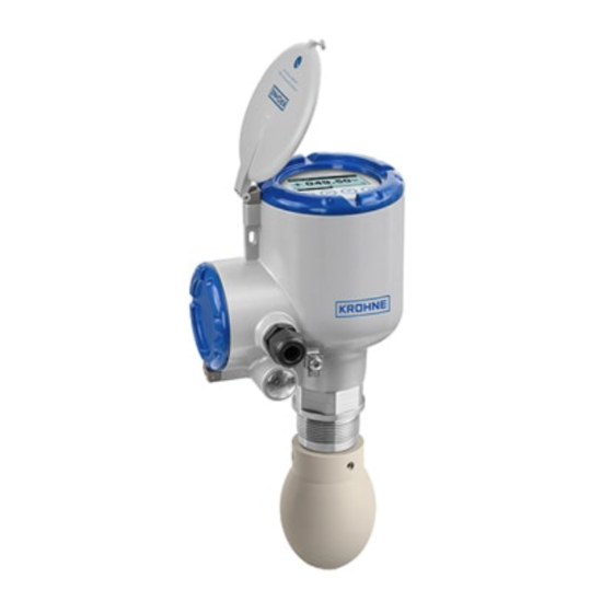
DEVICE DESCRIPTION OPTIWAVE 5400 C 2.2 Device description This device is a 24 GHz FMCW-radar level transmitter. It is a non-contact technology and is 2-wire loop-powered. It is designed to measure the distance, level, mass, volume and reflectivity Measuring of liquids, pastes and slurries. For more data about the measuring principle, refer to principle on page 133. -
Page 20: Visual Check
DEVICE DESCRIPTION OPTIWAVE 5400 C 2.3 Visual Check WARNING! If the display screen glass is broken, do not touch. INFORMATION! Inspect the packaging carefully for damages or signs of rough handling. Report damage to the carrier and to the local office of the manufacturer. -
Page 21: Nameplates
DEVICE DESCRIPTION OPTIWAVE 5400 C 2.4 Nameplates INFORMATION! Look at the device nameplate to ensure that the device is delivered according to your order. Check for the correct supply voltage printed on the nameplate. 2.4.1 Nameplate (examples) Figure 2-5: Non-Ex nameplate attached to the housing... -
Page 22: Installation
INSTALLATION OPTIWAVE 5400 C 3.1 General notes on installation INFORMATION! Inspect the packaging carefully for damages or signs of rough handling. Report damage to the carrier and to the local office of the manufacturer. INFORMATION! Do a check of the packing list to make sure that you have all the elements given in the order. -
Page 23: Transport
INSTALLATION OPTIWAVE 5400 C 3.3 Transport Figure 3-2: How to lift the device WARNING! Lift the device carefully to prevent damage to the antenna. If you remove the signal converter to lift the device, do not interchange this part with a different signal converter. This can have an effect on the performance of the device. -
Page 24: Pressure And Temperature Ranges
INSTALLATION OPTIWAVE 5400 C 3.5 Pressure and temperature ranges WARNING! The process connection temperature range must agree with the temperature limits of the gasket material. The operating pressure range is subject to the process connection used and the flange temperature. -
Page 25: Recommended Mounting Position
INSTALLATION OPTIWAVE 5400 C 3.6 Recommended mounting position CAUTION! Follow these recommendations to make sure that the device measures correctly. They have an effect on the performance of the device. We recommend that you prepare the installation when the tank is empty. - Page 26 INSTALLATION OPTIWAVE 5400 C Point the device in the correct direction to get the best performance Figure 3-5: Point the device in the correct direction to get the best performance 1 Cable entry 2 Nearest tank wall 3 Tank centerline Point the cable entries on the housing in the direction of the tank centerline.
-
Page 27: Tanks With Dish-Shaped And Conical Bottoms
INSTALLATION OPTIWAVE 5400 C 3.6.2 Tanks with dish-shaped and conical bottoms Dish-shaped or conical bottoms have an effect on the measuring range. The device cannot measure to the bottom of the tank. If possible, install the device as shown in the illustration that... -
Page 28: Mounting Restrictions
INSTALLATION OPTIWAVE 5400 C 3.7 Mounting restrictions CAUTION! Follow these recommendations to make sure that the device measures correctly. They have an effect on the performance of the device. We recommend that you prepare the installation when the tank is empty. - Page 29 INSTALLATION OPTIWAVE 5400 C Figure 3-8: Equipment and obstacles: how to prevent measurement of interference signals 1 Do not tilt the device more than 2° 2 We recommend that you do an empty spectrum recording if there are too many obstacles in the radar beam (for more...
-
Page 30: Process Connections
INSTALLATION OPTIWAVE 5400 C Product inlets Figure 3-9: Product inlets 1 The device is in the correct position. 2 The device is too near to the product inlet. CAUTION! Do not put the device near to the product inlet. If the product that enters the tank touches the antenna, the device will measure incorrectly. - Page 31 INSTALLATION OPTIWAVE 5400 C Recommended nozzle size for flange connections The nozzle must be as short as possible. Refer to the table below for the maximum height of the nozzle: Nozzle and antenna diameter, Maximum nozzle height, h Ød Metallic Horn antenna...
- Page 32 INSTALLATION OPTIWAVE 5400 C If the antenna diameter is larger than the process connection size (flange) Figure 3-11: How to attach the device if the antenna diameter is larger than the process connection size Special equipment needed: • 3-mm Allen wrench (not supplied) WARNING! If you attach the antenna in a closed space, make sure that there is a good airflow in the area.
- Page 33 INSTALLATION OPTIWAVE 5400 C General • Make sure that you point the device in the correct direction. For more data, refer to notes on page 25 ("Point the device in the correct direction"). • Tighten the flange bolts. Refer to local rules and regulations for the correct torque to apply to the bolts.
- Page 34 INSTALLATION OPTIWAVE 5400 C WARNING! Do not tighten the process connection to a torque more than 40 N m / 29.5 lbf ft. If the · · connection is too tight, this will damage the thread. To prevent damage to the antenna, make sure that the minimum diameter of the hole for a 1 1/2 NPT thread connection is not less than 43.4 mm / 1.71...
- Page 35 INSTALLATION OPTIWAVE 5400 C • Drop antennas without an extension: Drop antennas without an extension: Drop antennas without an extension: Remove the three locking screws with a 3-mm Allen Drop antennas without an extension: wrench. • Remove the antenna from the part below the flange (if there are no antenna extensions). If the device has one or more antenna extensions, remove the locking screw from the top antenna extension and remove the antenna and the antenna extensions from the part below the flange.
-
Page 36: Lpr Devices: Recommendations For Pits And Tanks Made Of Non-Conductive Materials
INSTALLATION OPTIWAVE 5400 C 3.7.3 LPR devices: recommendations for pits and tanks made of non-conductive materials WARNING! These instructions are for LPR equipment only. For more data, refer to Radio approvals on page Device installation on tanks made of a non-conductive material... -
Page 37: Standpipes (Stilling Wells And Bypass Chambers)
INSTALLATION OPTIWAVE 5400 C 3.7.4 Standpipes (stilling wells and bypass chambers) These instructions are applicable for devices with Metallic Horn antenna options only. Use a standpipe if: • There is highly conductive foam in the tank. • The liquid is very turbulent or agitated. - Page 38 INSTALLATION OPTIWAVE 5400 C Stilling wells – general notes CAUTION! You must drill an air circulation hole. Installation in tanks containing one liquid and foam • Drill an air circulation hole (max. Ø10 mm / 0.4¨) in the stilling well above the maximum level.
- Page 39 INSTALLATION OPTIWAVE 5400 C Stilling wells: horizontal cylindrical tanks We recommend that you install the device in a stilling well if the device: • is for a horizontal cylindrical tank, • is in a metallic tank, • measures a product with a high dielectric constant and •...
- Page 40 INSTALLATION OPTIWAVE 5400 C Bypass chambers Installation next to tanks containing one liquid and foam • The top process connection of the bypass chamber must be above the maximum level of liquid. • The bottom process connection of the bypass chamber must be below the lowest measured level of liquid.
-
Page 41: How To Attach Antenna Extensions
INSTALLATION OPTIWAVE 5400 C 3.8 How to attach antenna extensions If the device is not supplied with the antenna attached to the signal converter or antenna extensions are supplied as an accessory after delivery of the device, do the procedures that follow. - Page 42 INSTALLATION OPTIWAVE 5400 C • Push [> > > > ] to change the value. Push [> > > > ] to change the position of the cursor. Push [ ] to decrease the value or [ ] to increase the value. Minimum recommended blocking distance = antenna length + (antenna extension length ×...
- Page 43 INSTALLATION OPTIWAVE 5400 C Procedure 1: How to attach an antenna extension 1 Remove the O-rings from the plastic sachet supplied with the device. Put an O-ring 4 into the groove at the top of each antenna extension. 2 Attach the antenna extensions 1 below the flange. Use a 36-mm open-end wrench to tighten each antenna extension.
-
Page 44: How To Turn Or Remove The Display Module (Option)
INSTALLATION OPTIWAVE 5400 C 3.9 How to turn or remove the display module (option) If there is an object adjacent to the device that makes it difficult to read the display, you can rotate the display in increments of 90°. -
Page 45: Weather Protection
INSTALLATION OPTIWAVE 5400 C • Use the display extractor to remove the display module from the housing. Put the display extractor in the slots on the module for these clips. • Carefully remove the display module from housing and then remove the display extractor from the display module. - Page 46 INSTALLATION OPTIWAVE 5400 C Figure 3-24: Installation of the weather protection 1 Put the weather protection clamp around the top of the device. 2 Attach the two locking nuts to the threads on the weather protection clamp. Tighten the lock- ing nuts with a 10-mm socket wrench.
-
Page 47: How To Open The Weather Protection
INSTALLATION OPTIWAVE 5400 C 3.10.2 How to open the weather protection Figure 3-25: How to open the weather protection 1 Remove the R-clip from the hole at the front of the weather protection cover. 2 Remove the weather protection cover. -
Page 48: Electrical Connections
ELECTRICAL CONNECTIONS OPTIWAVE 5400 C 4.1 Safety instructions DANGER! All work on the electrical connections may only be carried out with the power disconnected. Take note of the voltage data on the nameplate! DANGER! Observe the national regulations for electrical installations! DANGER! For devices used in hazardous areas, additional safety notes apply;... -
Page 49: Electrical Installation: Output Options With Cable Gland
ELECTRICAL CONNECTIONS OPTIWAVE 5400 C 4.3 Electrical installation: output options with cable gland Figure 4-1: Terminals for electrical installation: standard cable gland 1 Internal grounding terminal (for the shield wire) 2 Current output - 3 Current output + 4 Internal grounding terminal... - Page 50 ELECTRICAL CONNECTIONS OPTIWAVE 5400 C Figure 4-2: How to open the terminal compartment cover Equipment needed: • 3-mm Allen wrench (not supplied) • Cover wrench Procedure 1 Loosen the lock screw with a 3-mm Allen wrench. 2 Remove the cover stop.
- Page 51 ELECTRICAL CONNECTIONS OPTIWAVE 5400 C Figure 4-3: Procedure for electrical installation Equipment needed: • POZIDRIV® PZ1 screwdriver (not supplied) Procedure 1 Loosen the cable gland. Put the electrical wires into the cable entry. Loosen the terminal screws with a POZIDRIV® PZ1 screwdriver. Connect the electrical wires to the connector.
- Page 52 ELECTRICAL CONNECTIONS OPTIWAVE 5400 C Figure 4-4: How to close the terminal compartment cover Equipment needed: • 3-mm Allen wrench (not supplied) 1 Put the cover on the housing 2 Turn the cover clockwise until it is fully engaged. 3 Attach the cover stop and lock screw.
-
Page 53: Electrical Installation: Output Options With An M12 Male Connector
ELECTRICAL CONNECTIONS OPTIWAVE 5400 C 4.4 Electrical installation: output options with an M12 male connector Figure 4-5: Terminals for electrical installation: 4-pin male M12 connector 1 Pin 1: current output + 2 Pin 2: not connected 3 Pin 3: current output -... -
Page 54: Devices For Hazardous Locations
ELECTRICAL CONNECTIONS OPTIWAVE 5400 C 4.5.2 Devices for hazardous locations DANGER! For electrical data for device operation in hazardous locations, refer to the related certificates of compliance and supplementary instructions (ATEX, IECEx etc.). This documentation can be downloaded from the website (Download Center). -
Page 55: Networks
ELECTRICAL CONNECTIONS OPTIWAVE 5400 C 4.7 Networks 4.7.1 General information The device uses the HART® communication protocol. This protocol agrees with the HART® Communication Foundation standard. The device can be connected point-to-point. It can also have a polling address of 1 to 63 in a multi-drop network. -
Page 56: Multi-Drop Networks
ELECTRICAL CONNECTIONS OPTIWAVE 5400 C 4.7.3 Multi-drop networks Figure 4-9: Multi-drop network (non-Ex) 1 Address of the device (each device must have a different address in multidrop networks) 2 4 mA + HART® 3 Resistor for HART® communication (typically 250 ohms) 4 Power supply 5 HART®... -
Page 57: Start-Up
START-UP OPTIWAVE 5400 C 5.1 Start-up checklist Check these points before you energize the device: • Are all the wetted components (antenna, flange and gaskets) chemically resistant to the product in the tank? • Does the information on the signal converter nameplate agree with the operating data? •... -
Page 58: Digital Display Screen
START-UP OPTIWAVE 5400 C 5.4 Digital display screen If you remove the housing cover, you can push the buttons on the keypad. If you cannot remove Keypad the housing cover, you can operate the keypad with a bar magnet. For more data, refer to buttons on page 59. -
Page 59: Keypad Buttons
START-UP OPTIWAVE 5400 C Display in Program mode Figure 5-2: Display screen layout in Program mode 1 Menu number or menu item number 2 Location (menu) of sub-menu or menu item 3 Menu item name 5.4.2 Keypad buttons Functions of keypad buttons... - Page 60 START-UP OPTIWAVE 5400 C How to push the keypad buttons with your hand Figure 5-3: How to push the keypad buttons with your hand Equipment needed • Cover wrench 1 Remove the housing cover with the cover wrench supplied with the device.
-
Page 61: Remote Communication With Pactware
START-UP OPTIWAVE 5400 C INFORMATION! It is not necessary to remove the display housing cover to do this procedure. • Hold the bar magnet near to a keypad button. The keypad button will operate. If you must operate the button more than one time, remove the bar magnet and then hold it near to the button again. -
Page 62: Remote Communication With The Ams™ Device Manager
START-UP OPTIWAVE 5400 C 5.6 Remote communication with the AMS™ Device Manager The AMS™ Device Manager is an industrial Plant Asset Management (PAM) software tool. Its role is to: • Store configuration information for each device. • Store and read process data. -
Page 63: Operation
OPERATION OPTIWAVE 5400 C 6.1 User modes Normal mode Normal mode This mode shows measurement data and status messages. For more data Normal mode Normal mode about measurements, refer to Normal mode on page 63. For more data Status messages and diagnostic data about status messages, refer to page 115. - Page 64 OPERATION OPTIWAVE 5400 C INFORMATION! Current output and LCD display settings Current output and LCD display settings Current output and LCD display settings Current output and LCD display settings When you do the Standard setup Standard setup procedure, the measurement value on the first measurement...
- Page 65 OPERATION OPTIWAVE 5400 C INFORMATION! How to change the number of digits and decimal places in the measurement values shown in How to change the number of digits and decimal places in the measurement values shown in How to change the number of digits and decimal places in the measurement values shown in...
- Page 66 OPERATION OPTIWAVE 5400 C Measurement type definitions Measurement type Description Available units Level This is a display and an output function option. m, cm, mm, in (inches), It is the height from the bottom of the tank to ft (feet), custom length unit the surface of the liquid (Tank height - Distance).
-
Page 67: Program Mode
OPERATION OPTIWAVE 5400 C 6.3 Program mode 6.3.1 General notes Change the settings of your device in Program Mode Program Mode. Data about the menus is given on page 81. Program Mode Program Mode You can: • Use the A Quick Setup... -
Page 68: Protection Of The Device Settings (Access Levels)
OPERATION OPTIWAVE 5400 C 6.3.2 Protection of the device settings (access levels) The settings of this device have three different access levels: "User", "Operator" and "Expert". "Expert" is the highest access level. The highest access level lets you change all available functions. - Page 69 OPERATION OPTIWAVE 5400 C • Push [> > > > ] to enter menu item C7.2.1 Login. • Enter the password used at this time for a given access level ("Operator" or "Expert"). If it is the default password, refer to the value given in the "Access levels and applicable functions in Program mode"...
-
Page 70: How To Get Access To The Quick Setup Menu
OPERATION OPTIWAVE 5400 C 6.3.3 How to get access to the Quick Setup menu The Quick Setup menu contains the menu items that are necessary for most configurations of the device. The menu items are divided into 2 groups: "Standard Setup" and "Empty Spectrum". -
Page 71: Keypad Functions
OPERATION OPTIWAVE 5400 C 6.3.4 Keypad functions Menu navigation Figure 6-4: Menu navigation 1 Menu number or menu item number 2 Location (menu) of sub-menu or menu item 3 Menu item name This is what you see when you are in Program mode. The functions of the buttons are given in the... - Page 72 OPERATION OPTIWAVE 5400 C Lists of parameters in menu items Figure 6-5: Lists of parameters in menu items 1 Menu item with parameter stored at this time (first screen). Push [> > > > ] to enter the menu item.
- Page 73 OPERATION OPTIWAVE 5400 C Values in menu items Figure 6-6: Values in menu items 1 Menu item with values stored at this time (first screen). Push [> > > > ] to enter the menu item. A cursor shows on the first digit.
-
Page 74: How To Save Settings Changed In Program Mode
OPERATION OPTIWAVE 5400 C INFORMATION! Values in menu items Values in menu items Values in menu items Values in menu items If the digit is part of a custom unit name, then refer to the list of available characters that... -
Page 75: Menu Overview
OPERATION OPTIWAVE 5400 C 6.3.6 Menu overview Menu overview: A – Quick Setup Normal Program Menu A Submenus ↓ ↑ ↓ ↑ ↓ ↑ > ^ > ^ > ^ > ^ A Quick Setup A Quick Setup A Quick Setup... - Page 76 OPERATION OPTIWAVE 5400 C Menu overview: B – Test Normal Program Menu B Submenus ↓ ↑ ↓ ↑ ↓ ↑ ↓ ↑ > > ^ > ^ > ^ > ^ B Test B Test B Test B Test B1 Simulation...
- Page 77 OPERATION OPTIWAVE 5400 C Menu overview: C – Full Setup Normal Program Menu C Submenus ↓ ↑ ↓ ↑ ↓ ↑ ↓ ↑ > > ^ > ^ > ^ > ^ C Full Setup C Full Setup C Full Setup C Full Setup C1 Install.
- Page 78 OPERATION OPTIWAVE 5400 C Normal Program Menu C Submenus ↓ ↑ ↓ ↑ ↓ ↑ ↓ ↑ > > ^ > ^ > ^ > ^ C Full Setup C Full Setup C4 Output C4 Output C4.1 C4.1 C4.1.1 Current Out. 1 Var.
- Page 79 OPERATION OPTIWAVE 5400 C Normal Program Menu C Submenus ↓ ↑ ↓ ↑ ↓ ↑ ↓ ↑ > > ^ > ^ > ^ > ^ C Full Setup C Full Setup C5.1 HART C5.1 HART C5.1.1 Current Loop Mode...
- Page 80 OPERATION OPTIWAVE 5400 C Normal Program Menu C Submenus ↓ ↑ ↓ ↑ ↓ ↑ ↓ ↑ > > ^ > ^ > ^ > ^ C Full Setup C Full Setup C6 Display C6 Display C6.4 1st Meas. page C6.4 1st Meas.
-
Page 81: Function Description
OPERATION OPTIWAVE 5400 C Normal Program Menu C Submenus ↓ ↑ ↓ ↑ ↓ ↑ ↓ ↑ > > ^ > ^ > ^ > ^ C Full Setup C Full Setup C7 Device C7 Device C7.5 Units C7.5 Units C7.5.1 Length... - Page 82 OPERATION OPTIWAVE 5400 C Menu Function Function description Selection list Default Login Enter the appropriate password here 4-digit hexadecimal password Refer to to change settings. If you do not enter "Function the password, you can only change description settings for the "user" access level.
- Page 83 OPERATION OPTIWAVE 5400 C B – Test menu Menu Function Function description Selection list Default B1 Simulation B1.1 Set Value B1.1 Set Value B1.1 Set Value B1.1 Set Value B1.1.2 Level This sets the device to a given test level min-max: value.
- Page 84 OPERATION OPTIWAVE 5400 C Menu Function Function description Selection list Default B1.1.5 Level Lin. This sets the device to a given test level min-max: value (linearized). This menu item is -5000.0...+5000.0 m / only available if you set up a -196.85...
- Page 85 OPERATION OPTIWAVE 5400 C Menu Function Function description Selection list Default B1.1.8 Distance Lin. This sets the device to a given test min-max: distance value (linearized). This menu -5000.0...+5000.0 m / item is only available if you set up a -196.85...
- Page 86 OPERATION OPTIWAVE 5400 C Menu Function Function description Selection list Default B1.2 Output B1.2 Output B1.2 Output B1.2 Output B1.2.1 Current Output 1 This sets analogue output 1 to a test 3.6...21.5 mA value [mA]. Output will change to the selected value, independent of the measured value.
- Page 87 OPERATION OPTIWAVE 5400 C Menu Function Function description Selection list Default B2.11 Ullage Volume This menu item shows the ullage Read only — volume readings measured at this time. This measurement data is shown with the units set in menu C7.5 Units C7.5 Units...
- Page 88 OPERATION OPTIWAVE 5400 C C – Full Setup menu Menu Function Function description Selection list Default C1 Install. Parameters C1.1 Tank Type The conditions in which the device is used. If Agitator, Stilling Well, Process the surface of the product is flat, select Process, Storage "Storage".
- Page 89 OPERATION OPTIWAVE 5400 C Menu Function Function description Selection list Default C1.7 Antenna Type The type of antenna attached to the device. If Metallic Horn (DN40), As specified in you change the antenna, this setting will Metallic Horn (DN50), the customer have an effect on C1.2 Tank Height and C1.5...
- Page 90 OPERATION OPTIWAVE 5400 C Menu Function Function description Selection list Default C2.3 Epsilon R Gas A major parameter for radar level 1.0...20 measurement devices. This can be applicable to high pressure applications or tanks that contain a specified gas. If the gas is not 1.0, set the ε...
- Page 91 OPERATION OPTIWAVE 5400 C Menu Function Function description Selection list Default C2.7 Mult. Refl. Multiple reflections will cause the device to Disabled, Enabled Disabled Enable display smaller level readings. Installation of the device on a manhole or at the centre of a dome roof, and high dielectric products (εr >5) can cause multiple reflections.
- Page 92 OPERATION OPTIWAVE 5400 C Menu Function Function description Selection list Default C3.2 Input Table C3.2 Input Table C3.2 Input Table C3.2 Input Table C3.2.2 Point This adds a point on the conversion table. min-max: Each time you enter this menu item, this 001...050...
- Page 93 OPERATION OPTIWAVE 5400 C Menu Function Function description Selection list Default C4.1.4 Current Out. This menu item sets the limits of the output 4-20 mA, 4-20 mA Range current range to 1 of 4 available options: 3.8-20.5 mA (NAMUR), standard limits (4...20 mA), NAMUR NE 43- 4-20 mA (reversed), compliant limits (3.8...20.5 mA), reversed...
- Page 94 OPERATION OPTIWAVE 5400 C Menu Function Function description Selection list Default C5 Communication C5.1 HART C5.1 HART C5.1 HART C5.1 HART C5.1.1 Current Loop Set this menu item to "On" if the "Primary On, Off Mode Variable" for current output 1 must also be transmitted as a 4…20 mA signal.
- Page 95 OPERATION OPTIWAVE 5400 C Menu Function Function description Selection list Default C5.1.3.2 Message You can give more data in this menu item — — (32 characters maximum). Minimum access level to change the Minimum access level to change the Minimum access level to change the...
- Page 96 OPERATION OPTIWAVE 5400 C Menu Function Function description Selection list Default C6.4 1st Meas. Page C6.4 1st Meas. Page C6.4 1st Meas. Page C6.4 1st Meas. Page C6.4.1 Function This menu item changes the configuration One Value, One Value &...
- Page 97 OPERATION OPTIWAVE 5400 C Menu Function Function description Selection list Default C6.4.8 3rd Value This changes the measurement type of the Level, Distance, Reflection Variable third value on the measurement page. This Sensor Value, Reflection, menu item is only available if you set C6.4.1 CO Percent Function to "Three Values".
- Page 98 OPERATION OPTIWAVE 5400 C Menu Function Function description Selection list Default C6.5.6 2nd Value This changes the measurement type of the Level, Distance, Level Variable second value on the measurement page. Sensor Value, Reflection, This menu item is only available if you set CO Percent C6.5.1 Function to "Two Values", "Two...
- Page 99 OPERATION OPTIWAVE 5400 C Menu Function Function description Selection list Default C7.1.9 Calibration Date This the date that the manufacturer Read only — calibrated the device. The date format is: Year-Month-Day. C7.2 Security C7.2 Security C7.2 Security C7.2 Security C7.2.1...
- Page 100 OPERATION OPTIWAVE 5400 C Menu Function Function description Selection list Default C7.5.3 Volume The volume unit shown in Normal mode if m³, L, hL, in³, ft³, gal, m³ you made a volume table in the C3 ImpGal, yd³, bbl, bbl Conversion menu.
-
Page 101: Further Information On Device Configuration In Program Mode
OPERATION OPTIWAVE 5400 C 6.4 Further information on device configuration in Program mode 6.4.1 Standard setup Use this procedure (menu item A4.1 Standard Setup) to change the length unit, tank type, tank height (this includes the stilling well diameter and stilling well height if Tank Type... - Page 102 OPERATION OPTIWAVE 5400 C Screen Steps Description • [ ] or [ ] for the selection of the Tank type. Make a selection from the list of parameters. If the surface of the product is tank type (Storage, Stilling Well, flat, select "Storage".
- Page 103 OPERATION OPTIWAVE 5400 C Screen Steps Description • [> > > > ] to change the position of the 100% range. Use this step to give the 100% output setting in the tank. Refer to the cursor. illustrations that follow. Illustration 1 •...
-
Page 104: Empty Spectrum Recording
OPERATION OPTIWAVE 5400 C Screen Steps Description • 3 × [^ ^ ^ ^ ] to confirm. Save Configuration? Save Configuration? screen. Save Configuration? Save Configuration? • [ ] or [ ] for the selection of the Set to "Yes" to save and use the settings save option (Yes, No or Back). - Page 105 OPERATION OPTIWAVE 5400 C Procedure Screen Steps Description • 2 × [> > > > ], 2 × [ ] and [> > > > ]. Default screen. Enter Program mode and go to menu item A3 Login. • If it is the default password: 2 × [> > > > ], Enter the password used at this time for the "Expert"...
-
Page 106: Hart® Network Configuration
OPERATION OPTIWAVE 5400 C Screen Steps Description • [ ] or [ ] to change the parameter Start recording? Set this menu item to "Yes" to continue to the subsequent step. ("No" or "Yes"). Set this menu item to "No" to go back to the •... -
Page 107: Distance Measurement
OPERATION OPTIWAVE 5400 C INFORMATION! Make sure that menu item C5.1.1 Current Loop Mode is set to "On". How to change from point-to-point to multi-drop mode • Enter Program mode. • Push 2 × [ ], [> > > > ], 3 × [ ], 2 × [> > > > ], [ ] and 2 × [> > > > ] to go to menu item C5.1.2.1 Polling Address. - Page 108 OPERATION OPTIWAVE 5400 C The flange facing (raised surface) is the reference point for distance measurement (e.g. 0 m / 0 ft / 0¨). If the device has a threaded connection, then the reference point is the thread stop. The position of the measurement scale (specified by the 0% Range and 100% Range settings) is related to this reference point.
-
Page 109: Level Measurement
OPERATION OPTIWAVE 5400 C INFORMATION! Bar graph function in Normal mode Bar graph function in Normal mode Bar graph function in Normal mode Bar graph function in Normal mode There is an optional bar graph shown on the two measurement pages in Normal mode (set C6.4.1 / C6.5.1 (Function) to "One Value &... - Page 110 OPERATION OPTIWAVE 5400 C CAUTION! If C4.1.1 Current Out. 1 Var. is set to "Level" and C4.1.3 100% Range (standard scale) is set in the blocking distance, then the device will not be able to use the full current output range.
-
Page 111: How To Configure The Device To Measure Volume Or Mass
OPERATION OPTIWAVE 5400 C 6.4.6 How to configure the device to measure volume or mass The device can be configured to measure volume or mass. It can also be configured to a custom quantity to be measured. You can set up a strapping table in the conversion menu (C3 Conversion). - Page 112 OPERATION OPTIWAVE 5400 C Figure 6-9: A plot of points for a volume or mass table 1 Tank with reference points 2 Tank model with plotted points How to delete a volume or mass table • Enter Program mode. • Push 2 × [ ], [> > > > ], 2 × [ ] and 2 × [> > > > ] to go to C3.1.1 Erase Table?.
-
Page 113: How To Measure Correctly In Tanks With Curved Or Conical Bottoms
OPERATION OPTIWAVE 5400 C 6.4.7 How to measure correctly in tanks with curved or conical bottoms It is possible that the device cannot find the bottom of the tank if it is installed in a tank with a dish-shaped or conical bottom. The form of the tank bottom causes a delayed radar reflection and the device will display the error message "Measurement is lost in the tank bottom". -
Page 114: How To Make A Filter To Remove Radar Signal Interference
OPERATION OPTIWAVE 5400 C 6.4.8 How to make a filter to remove radar signal interference If the device measures level in a tank that contains obstructions (agitator, supports, heating pipes etc.), these objects can cause radar signal interference (parasitic signals). You can use the empty spectrum function (menu A4.2) in the Quick Setup menu to make a filter to remove radar... -
Page 115: Status Messages And Diagnostic Data
OPERATION OPTIWAVE 5400 C 6.5 Status messages and diagnostic data Device status and error messages are shown on a device status page in Normal mode and in menu item "C7.3.1 Messages View" in Program mode. Messages shown agree with NAMUR Guidelines NE 107. - Page 116 OPERATION OPTIWAVE 5400 C Normal mode: device status messages There is also a device status page in Normal mode. This page shows a list of short status messages and gives the status of the device at this time. Push the [ ] or [ ] button to get to the status device status page in Normal mode.
- Page 117 OPERATION OPTIWAVE 5400 C Description of errors and corrective actions Status Error message Description Corrective action type F F F F Sensor Sensor Sensor Sensor Corrupt Sensor Parameter The sensor memory is bad. De-energize and then energize the device again.
- Page 118 OPERATION OPTIWAVE 5400 C Status Error message Description Corrective action type F F F F Configuration Configuration Configuration Configuration Inconsistent NVRAM Incorrect data in the parameter De-energize and then energize the memory. device again. If the message is shown again, tell the supplier.
- Page 119 OPERATION OPTIWAVE 5400 C Status Error message Description Corrective action type C C C C Electronics Electronics Electronics Electronics FW Update A firmware update of the Wait for the firmware update to converter module continues. finish. Configuration Configuration Configuration Configuration Sensor Sim.
- Page 120 OPERATION OPTIWAVE 5400 C Status Error message Description Corrective action type S S S S Electronics Electronics Electronics Electronics Elec. Temp. Out Of Spec. The temperature of the converter Make sure that the device is is not in the specified limits.
- Page 121 OPERATION OPTIWAVE 5400 C Status Error message Description Corrective action type M M M M Sensor Information Sensor Information Sensor Information Sensor Information Failed Sensor MCU Test The sensor electronics does a De-energize and then energize the continuous self-test procedure.
-
Page 122: Service
SERVICE OPTIWAVE 5400 C 7.1 Periodic maintenance 7.1.1 General notes In normal operational conditions, no maintenance is necessary. If it is necessary, maintenance must be done by approved personnel (the manufacturer or personnel approved by the manufacturer). INFORMATION! For more data about regular inspections and maintenance procedures for devices with Ex and other approvals, refer to the related supplementary instructions. -
Page 123: How To Clean The Top Surface Of The Device
SERVICE OPTIWAVE 5400 C CAUTION! Use multi-purpose grease that is applicable for the operating temperature range of the O-ring with the properties that follow: Operating temperature range of -40...+130 C / -40...+266 F without a negative effect on the •... -
Page 124: Service Warranty
SERVICE OPTIWAVE 5400 C 7.2 Service warranty WARNING! Only approved personnel can do an inspection of the device and repairs. If you find a problem, send the device back to your supplier for inspection and/or repairs. Servicing by the customer is limited by warranty to: •... -
Page 125: Returning The Device To The Manufacturer
SERVICE OPTIWAVE 5400 C 7.5 Returning the device to the manufacturer 7.5.1 General information This device has been carefully manufactured and tested. If installed and operated in accordance with these operating instructions, it will rarely present any problems. WARNING! Should you nevertheless need to return a device for inspection or repair, please pay strict... -
Page 126: Form (For Copying) To Accompany A Returned Device
SERVICE OPTIWAVE 5400 C 7.5.2 Form (for copying) to accompany a returned device CAUTION! To avoid any risk for our service personnel, this form has to be accessible from outside of the packaging with the returned device. Company: Address: Department:... -
Page 127: Disposal
SERVICE OPTIWAVE 5400 C 7.6 Disposal LEGAL NOTICE! Disposal must be carried out in accordance with legislation applicable in your country. Separate collection of WEEE (Waste Electrical and Electronic Equipment) in the European Union: Separate collection of WEEE (Waste Electrical and Electronic Equipment) in the European Union:... -
Page 128: Disassembly And Recycling
SERVICE OPTIWAVE 5400 C 7.7 Disassembly and recycling 7.7.1 General notes This section shows you how to handle the device if it is unserviceable (i.e. it is at the end of its product life cycle) or if it must be discarded. Information given in this section agrees with the EU Directive 2012/19/EU on waste electrical and electronic equipment (WEEE) and the EU Directive 2008/98/EC on waste (Waste Framework Directive) . - Page 129 SERVICE OPTIWAVE 5400 C Parts list Item Description Material Sun cover polyamid / PA12 Screw stainless steel Washer stainless steel Holder stainless steel Lock stainless steel Cover aluminium Cover aluminium Gasket EPDM Dummy display module polyamid / PA66 (10) (10)
- Page 130 SERVICE OPTIWAVE 5400 C Figure 7-2: Parts of the device (refer to the "Parts list" table) Equipment needed: • 3-mm Allen wrench (not supplied) • 5.5-mm socket wrench (not supplied) • POZIDRIV® PZ1 screwdriver (not supplied) • Adjustable wrench (not supplied) The product does not contain harmful gases or substances.
- Page 131 SERVICE OPTIWAVE 5400 C DANGER! De-energize the device before you disconnect the electrical cable. INFORMATION! Numbers in parentheses (xx) refer to item numbers in the parts list. Refer to the "Parts list" table and the related illustration in this section.
- Page 132 SERVICE OPTIWAVE 5400 C Materials and components which can be recycled Material Percentage of total weight Total weight [kg] [lb] Stainless steel 2.45 5.40 Aluminium Table 7-5: Materials and components which can be recycled www.krohne.com 01/2021 - 4005813703 - MA OPTIWAVE 5400 R03b en...
-
Page 133: Technical Data
TECHNICAL DATA OPTIWAVE 5400 C 8.1 Measuring principle A radar signal is emitted via an antenna, reflected from the product surface and received after a time t. The radar principle used is FMCW (Frequency Modulated Continuous Wave). The FMCW-radar transmits a high frequency signal whose frequency increases linearly during the measurement phase (called the frequency sweep). - Page 134 TECHNICAL DATA OPTIWAVE 5400 C Measurement modes "Direct" mode "Direct" mode "Direct" mode "Direct" mode ≥1.4), the level signal is the reflection on the If the dielectric constant of the liquid is high (ε surface of the liquid. "TBF Auto" mode "TBF Auto"...
-
Page 135: Technical Data
TECHNICAL DATA OPTIWAVE 5400 C 8.2 Technical data INFORMATION! • The following data is provided for general applications. If you require data that is more relevant to your specific application, please contact us or your local sales office. Additional information (certificates, special tools, software,...) and complete product •... - Page 136 TECHNICAL DATA OPTIWAVE 5400 C Beam angle Metallic Horn, DN40 (1.5¨): 17° (antenna) Metallic Horn, DN50 (2¨): 16° Metallic Horn, DN65 (2.5¨): not applicable. This antenna option is for the BM 26 A magnetic level indicator. Metallic Horn, DN80 (3¨): 9°...
- Page 137 TECHNICAL DATA OPTIWAVE 5400 C Pressure Pressure Pressure Pressure Process pressure Drop antenna (PP): Drop antenna (PP): Drop antenna (PP): Drop antenna (PP): -1…16 barg / -14.5…232 psig Metallic Horn antenna: Metallic Horn antenna: Metallic Horn antenna: Metallic Horn antenna: -1…16 barg / -14.5…232 psig...
- Page 138 TECHNICAL DATA OPTIWAVE 5400 C Process connections Thread G 1 A...1½ A (ISO 228); 1...1½ NPT (ASME B1.20.1) Flange version Flange version Flange version Flange version EN 1092-1 Low-pressure flanges: DN50...200 in PN01; Standard flanges: DN40 in PN40, DN50...200 in PN16 and PN40 (Type B1); others on...
- Page 139 TECHNICAL DATA OPTIWAVE 5400 C PROFIBUS PA PROFIBUS PA PROFIBUS PA PROFIBUS PA Type PROFIBUS MBP interface that agrees with IEC 61158-2 with 31.25 kbit/s; voltage mode (MBP = Manchester-Coded, Bus-Powered) Function blocks 1 × Transducer Block Level (TB-Level), 1 × Physical Block (PB), 4 × Analog Input Block (AI), 1 ×...
- Page 140 TECHNICAL DATA OPTIWAVE 5400 C Explosion protection Explosion protection Explosion protection Explosion protection ATEX (EU Type Approval) II 1/2 G Ex ia IIC T6...T* Ga/Gb; II 1/2 D Ex ia IIIC T85°C...T**°C Da/Db; II 1/2 G Ex db ia IIC T6...T* Ga/Gb;...
- Page 141 TECHNICAL DATA OPTIWAVE 5400 C Other standards and approvals Other standards and approvals Other standards and approvals Other standards and approvals SIL2/3 (SIL3: 1oo2 architecture is necessary for homogeneous redundancy) – certified according to all the requirements in EN 61508 (Full Assessment) and for high/low continuous demand mode operation.
-
Page 142: Measuring Accuracy
TECHNICAL DATA OPTIWAVE 5400 C 8.3 Measuring accuracy Use these graphs to find the measuring accuracy for a given distance from the transmitter. 0.1 0.2 Figure 8-2: Measuring accuracy (graph of measuring accuracy in mm against measuring distance in m) -
Page 143: Minimum Power Supply Voltage
TECHNICAL DATA OPTIWAVE 5400 C 8.4 Minimum power supply voltage Use these graphs to find the minimum power supply voltage for a given current output load. Non-Ex and Hazardous Location approved (Ex i / IS) devices Figure 8-4: Minimum power supply voltage for an output of 21.5 mA at the terminals (Non-Ex and Hazardous Location... -
Page 144: Guidelines For Maximum Operating Pressure
TECHNICAL DATA OPTIWAVE 5400 C 8.5 Guidelines for maximum operating pressure WARNING! Make sure that the devices are used within their operating limits. Figure 8-6: Pressure / temperature de-rating (EN 1092-1), flange and threaded connection, in °C and barg Figure 8-7: Pressure / temperature de-rating (EN 1092-1), flange and threaded connections, in °F and psig 1 Process pressure, p [barg] 2 Process connection temperature, T [°C]... - Page 145 TECHNICAL DATA OPTIWAVE 5400 C INFORMATION! CRN certification CRN certification CRN certification CRN certification There is a CRN certification option for devices with process connections that agree with ASME standards. This certification is necessary for all devices that are installed on a pressure vessel and used in Canada.
-
Page 146: Dimensions And Weights
TECHNICAL DATA OPTIWAVE 5400 C 8.6 Dimensions and weights Metallic Horn antennas with threaded connections Figure 8-10: Metallic Horn antennas with G or NPT threaded connections INFORMATION! • The diameter of the outer sheath of the cable must be 7 12 mm or 0.28... - Page 147 TECHNICAL DATA OPTIWAVE 5400 C Metallic Horn antennas with threaded connections: Dimensions in mm Horn antenna Dimensions [mm] version Øe DN40/1½¨ DN50/2¨ DN65/2½¨ DN80/3¨ DN100/4¨ DN150/6¨ DN200/8¨ Table 8-3: Metallic Horn antennas with threaded connections: Dimensions in mm 1 This is the dimension without the antenna extension option. A maximum of 10 antenna extensions are available. Each antenna exten- sion is 105 mm long.
- Page 148 TECHNICAL DATA OPTIWAVE 5400 C Metallic Horn antenna versions with standard flange connections Figure 8-11: Metallic Horn antennas with standard flange connections 1 Metallic Horn antenna with a flange connection INFORMATION! The diameter of the outer sheath of the cable must be 7 12 mm or 0.28...
- Page 149 TECHNICAL DATA OPTIWAVE 5400 C Metallic Horn antennas with standard flange connections: Dimensions in mm Horn antenna Dimensions [mm] version Øe DN40/1½¨ 203...215.6 130...143 333...358 DN50/2¨ 203...215.6 144...157 347...372 DN65/2½¨ 203...215.6 219...230 422...447 DN80/3¨ 203...215.6 254...267 457...482 DN100/4¨ 203...215.6 322...335 525...550...
- Page 150 TECHNICAL DATA OPTIWAVE 5400 C Metallic Horn antenna versions with low-pressure flange connections Figure 8-12: Metallic Horn antennas with low-pressure flange connections 1 Metallic Horn antenna with a low-pressure flange attached to a G threaded connection (ISO 228-1) 2 Metallic Horn antenna with a low-pressure flange attached to an NPT threaded connection (ASME B1.20.1) INFORMATION! •...
- Page 151 TECHNICAL DATA OPTIWAVE 5400 C Metallic Horn antennas with low-pressure flange connections: Dimensions in mm Horn antenna Dimensions [mm] version Øe DN40/1½¨ DN50/2¨ DN65/2½¨ DN80/3¨ DN100/4¨ DN150/6¨ DN200/8¨ Table 8-7: Metallic Horn antennas with low-pressure flange connections: Dimensions in mm 1 This is the dimension without the antenna extension option.
- Page 152 TECHNICAL DATA OPTIWAVE 5400 C Drop antennas with threaded connections Figure 8-13: Drop antennas with threaded connections INFORMATION! The diameter of the outer sheath of the cable must be 7 12 mm or 0.28 0.47 • … … ¨ Cable glands for cQPSus-approved devices must be supplied by the customer.
- Page 153 TECHNICAL DATA OPTIWAVE 5400 C Drop antennas with standard flange connections Figure 8-14: Drop antennas with standard flange connections 1 Drop antenna with a flange connection 2 Drop antenna with a flange connection and a flange plate protection option INFORMATION! •...
- Page 154 TECHNICAL DATA OPTIWAVE 5400 C Drop antennas with low-pressure flange connections Figure 8-15: Drop antennas with low-pressure flange connections 1 Drop antenna with a low-pressure flange attached to a G threaded connection (ISO 228-1) 2 Drop antenna with a low-pressure flange attached to an NPT threaded connection (ASME B1.20.1) INFORMATION! •...
- Page 155 TECHNICAL DATA OPTIWAVE 5400 C Purging option Figure 8-16: Purging options 1 1/8 NPTF threaded connection for purging system (the plug is supplied by the manufacturer) INFORMATION! Purging system Purging system Purging system Purging system This option is available for all Metallic Horn antennas. Flange connections must have a pressure rating of PN16 (EN 1092-1), PN40 (EN 1092-1), Class 150 (ASME B16.5), Class 300 (ASME B16.5),...
- Page 156 TECHNICAL DATA OPTIWAVE 5400 C Stainless-steel cover options Figure 8-17: Stainless-steel cover options 1 Signal converter housing with stainless-steel cover - without locking system 2 Signal converter housing with stainless-steel cover - with locking system Dimensions [mm] [inch] [mm] [inch] [mm] [inch] [mm] [inch] [mm] [inch] Without locking system 6.57...
- Page 157 TECHNICAL DATA OPTIWAVE 5400 C Weather protection option Figure 8-18: Weather protection option 1 Front view (with weather protection closed) 2 Left side (with weather protection closed) 3 Rear view (with weather protection closed) Dimensions Weights [kg] [mm] [inch] [mm]...
- Page 158 TECHNICAL DATA OPTIWAVE 5400 C Converter weight Type of housing Weights [kg] [lb] Compact aluminium housing Compact stainless-steel housing Table 8-17: Converter weight Antenna option weights Antenna options Min./Max. weights [kg] [lb] Standard options, without converter Standard options, without converter...
-
Page 159: Description Of Hart Interface
DESCRIPTION OF HART INTERFACE OPTIWAVE 5400 C 9.1 General description The HART® Protocol is an open digital communication protocol for industry. It is free to use by anyone. It is included in the software embedded in signal converters of HART-compatible devices. -
Page 160: Software History
DESCRIPTION OF HART INTERFACE OPTIWAVE 5400 C 9.2 Software history INFORMATION! In the table below, "x" is a placeholder for possible multi-digit alphanumeric combinations, depending on the available version. Release date Devices HART® Device Revision DD Revision 2016-04 All revisions Table 9-1: HART®... -
Page 161: Multi-Drop Connection (2-Wire Connection)
DESCRIPTION OF HART INTERFACE OPTIWAVE 5400 C 9.3.2 Multi-Drop connection (2-wire connection) Up to 63 devices may be installed in parallel (this signal converter and other HART® devices). For an illustration of multi-drop networks, refer to Multi-drop networks on page 56. -
Page 162: Operation
DESCRIPTION OF HART INTERFACE OPTIWAVE 5400 C • HART® Device Description file For more data, refer to the Field Communicator User’s Manual. 9.5.2 Operation INFORMATION! The Field Communicator will not give you access to the service menu. A simulation is only possible for current outputs. -
Page 163: Field Device Tool / Device Type Manager (Fdt / Dtm)
DESCRIPTION OF HART INTERFACE OPTIWAVE 5400 C 9.7 Field Device Tool / Device Type Manager (FDT / DTM) A Field Device Tool Container (FDT Container) is a PC program used to configure HART®, PROFIBUS and FOUNDATION™ fieldbus devices. To configure a device, an FDT container uses the applicable Device Type Manager (DTM). -
Page 164: Hart® Menu Tree For Ams
DESCRIPTION OF HART INTERFACE OPTIWAVE 5400 C 9.9 HART® menu tree for AMS Abbreviations of the following tables: • Optional, depending on device version and configuration • Read only 9.9.1 Overview AMS menu tree (positions in menu tree) Configure / Setup... -
Page 165: Ams Menu Tree (Details For Settings)
DESCRIPTION OF HART INTERFACE OPTIWAVE 5400 C 9.9.2 AMS menu tree (details for settings) Configure / Setup Quick Setup General Language / Tag / Long Tag Security Login / Change Password / Reset Passwords / Lock Status / Lock / Unlock Device / Write Protect... - Page 166 DESCRIPTION OF HART INTERFACE OPTIWAVE 5400 C Full Setup Device Information / Long Tag / Serial Number / Manufacturer Device Name / V Number Electronic Revision / Field Device Revision / Software Revision / Hardware Revision / Electronics Serial / Production Date...
- Page 167 DESCRIPTION OF HART INTERFACE OPTIWAVE 5400 C Device Diagnostics Device Status Condensed Status (NE 107) Condensed Status (NE 107) Device Simulation Active Standard Device Status / Ext. Device Status / Write Protect / Device Diagnostic Status 0 / Device Diagnostic Status 1...
-
Page 168: Hart® Menu Tree For Pdm
DESCRIPTION OF HART INTERFACE OPTIWAVE 5400 C 9.10 HART® menu tree for PDM Abbreviations of the following tables: • Optional, depending on device version and configuration • Read only Cust • Custody lock protection • Local PDM, affects only PDM views 9.10.1 Overview PDM menu tree (positions in menu tree) -
Page 169: Pdm Menu Tree (Details For Settings)
DESCRIPTION OF HART INTERFACE OPTIWAVE 5400 C Overview: Diagnosis Device Status Condensed Status (NE 107) Standard Additional Cluster Check Actual Values Simulation Process Variables Device Status Test / Reset Information Table 9-8: Overview: Diagnosis 9.10.2 PDM menu tree (details for settings) Device Menu Download To Device... - Page 170 DESCRIPTION OF HART INTERFACE OPTIWAVE 5400 C Display General Language / Backlight 1st Measurement Function / 1st Value Variable / Format 1st Value / Page 2nd Value Variable / Format 2nd Value / 3rd Value Variable / Format 3rd Value...
- Page 171 DESCRIPTION OF HART INTERFACE OPTIWAVE 5400 C View Menu Measurement Value Opt, Rd Opt, Rd Sensor Value / Media Level / Distance / Reflection / Level Linearization / Volume Opt, Rd Opt, Rd Opt, Rd Opt, Rd Mass / Distance Linearization...
-
Page 172: Appendix
APPENDIX OPTIWAVE 5400 C 10.1 Accessories: general items We supply accessories for this device. When you send an order for accessories, please give the reference numbers that follow: Figure 10-1: Accessories: general items 1 Weather protection 2 Viator RS232 / HART converter... -
Page 173: Accessories: Process Connection Kits For The Level Transmitter
APPENDIX OPTIWAVE 5400 C 10.2 Accessories: process connection kits for the level transmitter Figure 10-2: Accessories: process connection kits for the level transmitter 1 316L low-pressure flange disc for G (ISO 228) threaded connection option 2 316L low-pressure flange disc for NPT (ASME B1.20.1) threaded connection option 3 316L wall-mounted bracket for G 1½... -
Page 174: Glossary
APPENDIX OPTIWAVE 5400 C Item Description Bolt hole dimensions Quantity Part reference agree with: 316L low-pressure flange disc DN50 PN2.5...PN40 (EN) / XF70000N10 (max. 14.5 psig at +68°F) for NPS 2 Class 150 (ASME) 1½ NPT threaded connection DN100 PN2.5...PN40 (EN) /... - Page 175 APPENDIX OPTIWAVE 5400 C Hazardous area Hazardous area An area with a potentially explosive atmosphere. Trained personnel can Hazardous area Hazardous area install and use a device in this area. The device must be ordered with the appropriate options. The device requires approvals (ATEX, IECEx, cQPSus, NEPSI etc.) related to site specifications.
- Page 176 APPENDIX OPTIWAVE 5400 C Volume Volume Total volume of tank contents. Volume Volume Figure 10-3: Measurement definitions: distance 1 Distance 2 Blocking distance 3 Flange facing 4 Gas (Air) 5 Tank height 6 Ullage volume or mass Figure 10-4: Measurement definitions: level...
- Page 177 NOTES OPTIWAVE 5400 C 01/2021 - 4005813703 - MA OPTIWAVE 5400 R03b en www.krohne.com...
- Page 178 NOTES OPTIWAVE 5400 C www.krohne.com 01/2021 - 4005813703 - MA OPTIWAVE 5400 R03b en...
- Page 179 NOTES OPTIWAVE 5400 C 01/2021 - 4005813703 - MA OPTIWAVE 5400 R03b en www.krohne.com...
- Page 180 Engineering, commissioning, calibration, maintenance and training services Head Office KROHNE Messtechnik GmbH Ludwig-Krohne-Str. 5 47058 Duisburg (Germany) Tel.: +49 203 301 0 Fax: +49 203 301 10389 info@krohne.com The current list of all KROHNE contacts and addresses can be found at: www.krohne.com...
Need help?
Do you have a question about the OPTIWAVE 5400 C and is the answer not in the manual?
Questions and answers