Table of Contents
Advertisement
Quick Links
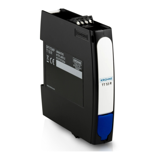
OPTITEMP TT 53 C/R
OPTITEMP TT 53 C/R
OPTITEMP TT 53 C/R
OPTITEMP TT 53 C/R
Smart 2-wire universal transmitter
®
with HART
7 and NFC technology
The documentation is only complete when used in combination with the relevant
documentation for the sensor.
© KROHNE 06/2018 - 4006523501 - MA OPTITEMP TT 53 R01 en
Handbook
Handbook
Handbook
Handbook
Advertisement
Table of Contents


Need help?
Do you have a question about the OPTITEMP TT 53 R Ex and is the answer not in the manual?
Questions and answers