Table of Contents
Advertisement
Quick Links
Advertisement
Table of Contents

Related Manuals for Inspur NF8380M5


Summary of Contents for Inspur NF8380M5
- Page 1 InspurServerUser Manual NF8380M5...
- Page 2 Inspur. The information in this manual is subject to change without notice. Inspur is the registered trademark of Inspur. All the other trademarks or registered trademarks mentioned in this manual are the property of their respective holders.
- Page 3 4.Please install the product-compatible operating system and use the driver provided by Inspur. If you use an incompatible operating system or non-Inspur driver, it may cause compatibility issues and affect the normal use of the product, Inspur will not assume any responsibility or liability.
-
Page 4: Table Of Contents
Contents 1 Safety Instructions ......................... 1 2 Product Specification ........................6 2.1 Introduction ..........................6 2.2 Features and Specifications ......................6 3 Component Identification ......................8 3.1FrontPanel Components ......................8 3.2Rear Panel Components ......................10 3.3MotherboardComponents ......................11 3.4MotherboardJumper Introduction ....................12 4 Operations ............................. - Page 5 7.1 Login to BIOS Interface ....................... 27 7.2 UEFI/Legacy Mode Switch ......................29 7.3 View System Information ......................29 7.4 View CPU Information ........................ 30 7.5 View Memory Information ......................31 7.6 View HDD Information and RAID Configuration ................. 31 7.7 BMC Network Parameters View and Settings................
- Page 6 11.4 European Union Regulatory Notice ..................124 11.5 Disposal of Waste Equipment by Users in the European Union ..........124 11.6 Korean Notice ........................... 125 11.7 Chinese Notice.......................... 125 11.8 Battery Replacement Notice ....................125 12Electrostatic Discharge ......................... 127 12.1 Preventing Electrostatic Discharge ................... 127 12.2 Grounding Methods to Prevent Electrostatic Discharge ............
-
Page 7: Safety Instructions
For your safety, please do not attempt to remove the cover of the system to remove or replace any component without assistance provided by Inspur. Only service technicians trained by Inspur are authorized to remove the cover of the host, and to remove and replace internal components. - Page 8 The following considerations may help avoid the occurrence of problems that could damage the components or cause data loss, etc. In the event of the following, please unplug the power line plug from the power socket and contact Inspur’s customer service department:...
- Page 9 Please remember that only service technicians trained by Inspur are authorized to remove the cover of the host, and to remove and replace internal components.
- Page 10 Upon receiving the proper authorization from Inspur and dismounting the internal components, please pay attention to the following: Switch the system power supply off and disconnect the cables, including all connections of the system.
- Page 11 Safety Introduction Do not overload the AC power supply branch circuits in the rack. The total load of the rack should not exceed 80% of the ratings of the branch circuits. Ensure that components in the rack have good ventilation conditions. When repairing components in the rack, never step on any other components.
-
Page 12: Product Specification
Olympusspecifications in the industry. It can be applied to large data centers and deployed in the enterprise server rooms, suitable for Internet AI, High Performance Computing (HPC), databases and other fields.Inspur NF8380M5 server can support HGX-1 GPU accelerator and FPGA acceleratorof the Olympus project, providing powerful acceleration and artificial intelligence computing;... - Page 13 Product Specification Management Port 1 front RJ45 IPMI port Display Controller Type Integrated inthe Aspeed2500chip, supports up to 1900*1200 resolution PCIe Extension Type Supports 9 PCIe X16 slots, can be matched according to the configuration Drive Supports SATA/M.2 disk Drive Type Supports up to: 37*M.2 + 1*3.5”...
-
Page 14: Component Identification
3 Component Identification 3.1FrontPanel Components 3.1.1 Front PanelView of GPUBOX Configuration Item Description Handle GPU BOX Riser slots PCIe Riser slots Handle Buttons& LEDs IO ports 3.1.2 Front Panel View of M.2Configuration Item Description Handle M.2 Riser slots PCIe Riser slots Handle Buttons &... - Page 15 Component Identification 3.1.3 Front Panel View of GPUConfiguration Item Description Handle GPU module slots Handle M.2 Riser slots Buttons & LEDs M.2 Riser slots IO ports 3.1.4 Front panel IO ports Item Description IPMI USB3.0 USB3.0...
-
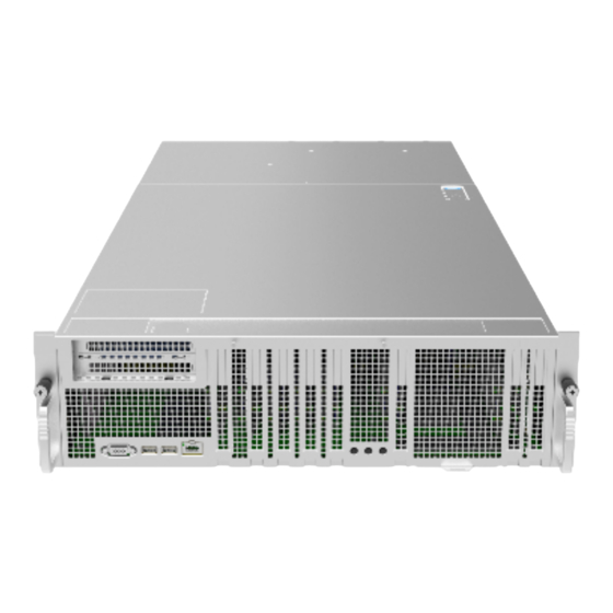
Page 16: Rear Panel Components
3.1.5 Front Panel Buttons & LEDs Item Description Attention LED UID Button LED Power Button LED 3.2 Rear Panel Components Item Description RM port System fans PSUs... -
Page 17: Motherboardcomponents
Component Identification 3.3 MotherboardComponents Item Description DIMM slots (CPU0) DIMM slots (CPU1) DIMM slots (CPU2) DIMM slots (CPU3) CPU0 CPU1 CPU2 CPU3 FAN0-FAN3 connectors FAN4-FAN7 connectors Power backplane_power connectors Power backplane_signal connector Slimline connector (PCIE x8) Slimline connector (PCIE x8) sSATA hard disk_power connector... -
Page 18: Motherboardjumper Introduction
Item Description sSATA hard disk_signal connector Slimline connector (PCIE x8) Slimline connector (PCIE x8) M.2 connectors Riser card expansion connectors Oculink connector TPM connector Attention LED UID Button LED Power Button LED BMC RJ45 network port USB3.0 port USB3.0 port VGA port PCIE x16 slots 3.4 MotherboardJumper Introduction... -
Page 19: Operations
Operations 4 Operations 4.1 Power up the Server Insert the power cord plug, then press the Power Button. 4.2 Power down the Server WARNING: To reduce the risk of personal injury, electric shock, or damage to the equipment, remove the power cord to remove power from the server. The front panel Power Button does not completely shut off system power. - Page 20 After performing the installation or maintenance procedure, slide the server back into the rack until it clicks into place. Tighten the screws to secure the chassis in place. WARNING: To reduce the risk of personal injury, be careful when sliding the server into the rack.
-
Page 21: Setup
Leave a minimum clearance of 121.9 cm (48 in) from the back of the rack to the back of another rack or row of racks. Inspur Servers draw in cool air through the front door and expel warm air through the rear door. Therefore, the front and rear rack doors must be adequately ventilated to allow ambient room air to enter the cabinet, and the rear door must be adequately ventilated to allow the warm air to escape from the cabinet. - Page 22 adequate airflow (equivalent to the required 64 percent open area for ventilation). • Side—The clearance between the installed rack component and the side panels of the rack must be a minimum of 7 cm (2.75 in). 5.1.2 Temperature Requirements To ensure continued safe and reliable equipment operation, install or position the system in a well-ventilated, climate-controlled environment.
-
Page 23: Rack Warnings
Because of the high ground-leakage currents associated with multiple servers connected to the same power source, Inspur recommends the use of a PDU that is either permanently wired to the building’s branch circuit or includes a nondetachable cord that is wired to an industrial-style plug. -
Page 24: Identifying The Contents Of The Servershipping Carton
WARNING: To reduce the risk of personal injury or equipment damage when unloading a rack: • At least two people are needed to safely unload the rack from the pallet. An empty 42U rack can weigh as much as 115 kg (253 lb), can stand more than 2.1 m (7 ft) tall, and may become unstable when being moved on its casters. -
Page 25: Installing The Operating System
5.6 Installing the Operating System To operate properly, the server must have a supported operating system installed. For the latest information on supported operating systems, refer to the Inspur website (http://www. inspur.com/eportal/ui?pageId=2317460). To install the operating system on the server, you can download from the official website... -
Page 26: Hardware Options Installation
6 Hardware Options Installation Introduction If more than one option is being installed, read the installation instructions for all the hardware options and identify similar steps to streamline the installation process. WARNING:To reduce the risk of personal injury from hot surfaces, allow the drives and theinternal system components to cool before touching them. - Page 27 Hardware Options Installation Remove the air baffle. Remove the heatsink. 6.Install the processor: Step 1:Align the Clip’s triangle markwith the CPU’s corner mark, and then assemble the Clip and CPU together. Step 2:Align the heatsink position marked by “1” with the Clip’s triangle mark, vertically align the mounting holes on the heatsink with those on the Clip, and assemble the heatsink andClip together.
-
Page 28: Memory Option
by “1” should be aligned with the triangle mark on the CPU socket. Tighten the screws according to the sequence of 1, 2, 3, 4. Notes: ● It is required to coat thermal grease evenly onto the contact position between CPU heatsink and CPU. - Page 29 Hardware Options Installation ● DIMM population guidelines: Step 1: Open the lock tabs on both ends of the DIMM slot. Step 2: Align the bottom key with the receptive point on the slot, press both ends of the...
-
Page 30: Redundant Hot-Plug Power Supply Option
DIMM with your thumbs. Insert the DIMM into the slot completely, and the lock tabs will automatically secure the DIMM, locking it into place. 6.3 Redundant Hot-plug Power Supply Option CAUTION:To prevent improper cooling and thermal damage, do not operate the server unless all bays are populated with either a component or a blank. -
Page 31: Air Baffle Option
Hardware Options Installation Connect the power cord to the power supply. Route the power cord through the power cord anchor or cable management arm. Reposition the cable management arm into the operating position. Connect the power cord to the power source. Verify that the corresponding power supply LED is green. - Page 32 the following figure.
-
Page 33: Bios Setup
Power on the server. The system will then start to boot. When the following content appears below Inspur logo on the screen: “Press <DEL> to SETUP or <TAB> to POST or <F11> to Boot Menu or <F12> to PXE Boot.” Press DEL key. When “Entering Setup …” appears in the lower right corner of the screen, it will enter the BIOS setup soon. - Page 34 • Press TAB to display the system information during POST. • Press F11 to enter the boot management interface, select the boot device. Press F12 to boot the PXE. • BIOS Setup Interface Control Key Instruction Table Function <Esc> Exit or return from submenu to main menu <←>...
-
Page 35: Uefi/Legacy Mode Switch
Storage, Video OPROM Policy and Other PCI devices, as shown in the following figure. At present, Inspur Purley platform servers are set to UEFI Mode by default. Compared with Legacy mode, UEFI mode has many advantages: It supports boot from the GPT disk which is larger than 2.2T, supports IPv6/IPv4 PXE boot, and provides UEFI Shell environment. -
Page 36: View Cpu Information
7.4 View CPU Information Login to the BIOS interface, select “Processor -> Processor Configuration -> Processor Information”, and press Enter to display the CPU detailed information, as shown in the following figure. -
Page 37: View Memory Information
BIOS Setup 7.5 View Memory Information Login to the BIOS interface, select “Processor -> Memory Configuration -> Memory Topology”, and press Enter to display the manufacturer, speed, capacity and other information of the memories in position, as shown in the following figure. 7.6 View HDD Information and RAID Configuration 7.6.1 View HDD Information Login to the BIOS interface, select “Chipset ->... - Page 38 7.6.2 RAID Mode Settings Set the SATA Mode Option to [RAID], press F10 to save the setting, and the system reboots. When Boot Mode is set to UEFI mode, in the BIOS Setup Advanced interface, there will be the Intel(R) RSTe SATA Controller menu, as shown in the following figure.
- Page 39 BIOS Setup Press Enter, the executable operation and the current disk information will be displayed, as shown in the following figure. Create RAID volume. Select Create RAID Volume option, and press Enter, as shown in the following figure.
- Page 40 Create RAID Menu Instruction Table Interface Parameters Function Description Please enter a volume name less than 16 characters without containing any special Name characters. Please select the RAID volume level. If no volume has been created at present, there are four volume levels of RAID0 (Stripe), RAID1 (Mirror), RAID10 (RAID0+1) and RAID5 (Parity) for selection.
- Page 41 BIOS Setup When Boot Mode is set to Legacy, a prompt “Press <CTRL-I> to enter Configuration Utility…” will appear on the screen during system booting. Press [Ctrl] and [I] keys at the...
- Page 42 same time to enter SATA RAID configuration, as shown in the following figure. After entering SATA RAID configuration interface, it will display the main menu list, the information (HDD ID, HDD type, HDD capacity, volume member or not) of HDDs connected to SATA controller, and the existed RAID volumes information (including volume ID, name, RAID level, capacity, status, bootable or not).
- Page 43 BIOS Setup Create RAID Volume menu. After entering SATA RAID configuration interface, you could use up and down arrow keys to select this menu, and then press Enter to enter the Create RAID Volume menu, or directly input the number before the menu to enter the Create RAID Volume menu.
- Page 44 enter “Y” to create an RAID volume. After the creation is completed, return to MAIN MENU interface, the created RAID volume will be displayed. 3.3 Delete RAID Volume menu. After entering Delete RAID Volume menu, press [DEL] to delete the selected RAID volume, and the system will prompt “ALL DATA IN THE VOLUME WILL BE LOST! Are you sure you want to delete “Volume0*”? (Y/N)”.
- Page 45 BIOS Setup Mask Disk as Spare menu. After entering Mask Disk as Spare menu, system will display the HDDs not in RAID volume. Please use the space key to select the HDDs according to the actual demand, and then press Enter. The system will prompt “Are you sure you want to mask selected disks as Spare? (Y/N)”, enter “Y”...
-
Page 46: Bmc Network Parameters View And Settings
7.7 BMC Network Parameters View and Settings 7.7.1 View BMC Network Parameters Login to the BIOS interface, select “Server Mgmt -> BMC Network Configuration -> BMC IPv4 Network Configuration/BMC IPv6 Network Configuration”. Press Enter to view the current configuration of BMC IPv4 and BMC IPv6 network, as shown in the following figures. - Page 47 BIOS Setup 7.7.2 BMC Network Settings Take BMC Sharelink port as an example to introduce the settings of BMC IPv4 network parameters, as shown in the following table. BMC Network Configuration Instruction Table Interface Parameters Function Description Default Value Set the way to get BMC network parameters, options include: Get BMC Sharelink /Dedicated Do Nothing...
- Page 48 If the setting succeeds, the system prompts “Set Static BMC Station IP OK!!!” Press Enter to confirm, and the IP will take effect immediately. If the setting fails, the system prompts “Set Static BMC Station IP Fail!!!” If the IP does not change, the system prompts “Static BMC Station IP Not Change!!!” If the input IP is invalid, the system prompts “Invalid Station IP Entered!!!”, and assign 0.0.0.0 to the IP address.
- Page 49 BIOS Setup 7.7.2.2 Set BMC Dynamic Network Parameters Set the Configuration Address Source option to [DynamiBmcDhcp]. If the setting succeeds, the system will prompt “Set Dynamic BMC IP Address Source Success! Dynamic BMC Network Parameters are Getting Now, Please Wait a Moment!”, as shown in the following figure. After pressing Enter to confirm, the following interface will stay for 30s, please wait patiently.
-
Page 50: Bios Parameter Description
Note: Please make sure that the BMC management port is connected to the network when you use the Manual setting options. The options that take effect immediately in the BIOS Setup interface are implemented by calling the Callback function. Callback functions are only called when the options in the BIOS Setup interface are changed. - Page 51 BIOS Setup Main Interface Instruction Table Interface Parameters Function Description Product Name Product name Serial Number Serial number Customer ID Customer ID BIOS Version BIOS version Build Date Build date BMC Firmware Version BMC FW version ME Firmware Version ME FW version Access Level Current access level CPU Information...
- Page 52 Advanced Interface Instruction Table Interface Parameters Function Description Trusted Computing Trusted computing configuration Super IO Configuration AST2400 I/O chip parameter configuration Serial Port Console Redirection Serial port console redirection settings PCI Subsystem Settings PCI subsystem settings Network Stack Configuration Network stack configuration CSM Configuration CSM configuration NVMe Configuration...
- Page 53 BIOS Setup 7.8.2.2 Super IO Configuration Super IO Configuration interface is used to set the options related with I/O chip. Super IO Configuration Interface Instruction Table Interface Parameters Function Description Serial port 0 configuration, the configuration interface provides this serial Serial Port 0 Configuration port’s on-off control and resource allocation control.
- Page 54 Serial Port 0 ConfigurationInterface Instruction Table Interface Parameters Function Description Default Value Serial port 0 on-off settings. Options include: Serial Port Enabled Enabled Disabled Select the optimal setting according to the demand. Options include: Auto Change Settings I0=3F8h; IRQ=4; Auto I0=3F8h;...
- Page 55 BIOS Setup Console Redirection Settings Interface Instruction Table Interface Parameters Function Description Default Value Terminal type settings. Options include: VT100 Terminal Type VT100+ ANSI VT-UTF8 ANSI Baud rate settings. Options include: 9600 19200 Bits per second 115200 38400 57600 115200 Serial port data width settings.
- Page 56 Recorder mode on-off settings. Options include: Recorder Mode Enabled Disabled Disabled Expanded redirection resolution 100×31 on-off settings. Options include: Redirection 100×31 Disabled Enabled Disabled Legacy OS redirection resolution settings. Options Legacy OS Redirection include: 80×24 Resolution 80×24 80×25 Putty function keys and keyboard settings. Options include: VT100 LINUX...
- Page 57 BIOS Setup 7.8.2.4Network Stack Configuration Network Stack Configuration interface is used to set the options related with Network UEFI PXE. Network Stack Configuration Interface Instruction Table Interface Parameters Function Description Default Value Network stack on-off settings. Options include: Enabled Disabled Network Stack Enabled Only this option is enabled, the following options can be displayed...
- Page 58 CSM Configuration Interface Instruction Table Interface Parameters Function Description Default Value CSM support on-off settings. Options include: CSM Support Enabled Disabled Disabled A20 line control mode settings. Options include: Upon Request GateA20 Active Always Upon Request A20 is an address line, which controls the system how to access the memory space larger than 1MB.
- Page 59 BIOS Setup 7.8.3 Chipset Chipset interface includes the information settings and runtime error logging settings of PCH SATA/sSATA, USB and ME devices. Chipset Interface Instruction Table Interface Parameters Function Description PCH SATA Configuration PCH SATA configuration PCH sSATA Configuration PCH sSATA configuration USB Configuration USB configuration Miscellaneous Configuration...
- Page 60 PCH SATA Configuration Interface Instruction Table Interface Parameters Function Description Default Value SATA controller on-off settings. Options include: SATA Controller Enabled Enabled Disabled SATA mode settings. Options include: SATA Mode Options AHCI AHCI RAID SATA Port 0~7 SATA port 0~7 HDD information ---- SATA port on-off settings.
- Page 61 BIOS Setup PCH sSATA Configuration Interface Instruction Table is omitted here. 7.8.3.2 USB Configuration USB Configuration is used to set the options related with the onboard USB ports. USB Configuration Interface Instruction Table Interface Parameters Function Description Default Value Onboard USB port on-off settings. Options include: USB N Enabled Enabled...
- Page 62 Miscellaneous Configuration Interface Instruction Table Interface Parameters Function Description Default Value Power state settings when restoring on AC power loss. Options include: Restore AC Power Loss Power OFF Power OFF Last State Power ON The maximum page table size settings. Options include: Max Page Table Size For older OS, please select 2MB, otherwise, it may cause a problem.
- Page 63 BIOS Setup PTT support on-off settings. Options include: PTT Support Enabled Disabled Disabled Altitude Altitude settings 8000 MCTP bus owner is located in PCIe: [15:8] bus, [7:3] MCTP Bus Owner device, [2:0] function. If set to 0, it means disabled. ME Firmware Features ME FW features ----...
- Page 64 Processor Interface Instruction Table Interface Parameters Function Description Processor Configuration Processor configuration Common Configuration Common configuration UPI Configuration UPI configuration Memory Configuration Memory configuration IIO Configuration IIO configuration Advanced Power Management Configuration Advanced power management configuration 7.8.4.1 Processor Configuration Processor Configuration interface is used to set the options related with the processor.
- Page 65 BIOS Setup Processor Configuration Interface Instruction Table Interface Parameters Function Description Default Value Processor information submenu, the processor’s detailed Processor Information ---- information CPU core settings. Input the number of CPU cores you want to enable. In the Help information, it will display the effective Active Cores values you can set and the maximum number of physical cores according to the current CPU usage.
- Page 66 Hardware prefetcher on-off settings. Options include: Enabled Disabled Before CPU processing instructions or data, it will prefetch Hardware Prefetcher Enabled these instructions or data from memory to L2 cache, to shorten the amount of time that reading memory takes, to help eliminate potential bottlenecks and to improve system performance.
- Page 67 BIOS Setup 7.8.4.2 Common Configuration Common Configuration interface is used to set the common options. Common Configuration Interface Instruction Table Interface Parameters Function Description Default Value MMIO high base settings. Options include: MMIO High Base MMIO high granularity size settings. Options include: MMIO High Granularity Size 256G 256G...
- Page 68 UPI Configuration Interface Instruction Table Interface Parameters Function Description Default Value UPI Status UPI status submenu, displaying the current UPI link status ---- Degrade precedence settings. Options include: Topology Precedence Feature Precedence Topology Degrade Precedence When the system settings conflict, set it to Topology Precedence Precedence to reduce Feature;...
- Page 69 BIOS Setup Sub NUMA cluster settings. Options include: Auto: Support 1-cluster or 2-clusters according to IMC interleave. Sub NUMA Clustering Enabled: Support all SNC clusters (2-clusters) and 1-way IMC Disabled interleave. Disabled: SNC function not supported. Legacy VGA Socket Legacy VGA number settings, the range of effective values is 0~1. 0 Legacy VGA stack number settings, the range of effective values is Legacy VGA Stack 0~6.
- Page 70 DDR4 data scrambling on-off settings. Options include: Auto Data Scrambling for DDR4 Enabled Enabled Disabled ADR on-off settings. Options include: Enable ADR Enabled Enabled Disabled Legacy ADR mode on-off settings. Options include: Legacy ADR Mode Enabled Enabled Disabled ADR data save mode settings. Options include: Disabled ADR Data Save Mode NVDIM...
- Page 71 BIOS Setup Memory Map Interface Instruction Table Interface Parameters Function Description Default Value Volatile memory mode settings. Options include: Volatile Memory Mode Auto 1LM memory interleave granularity settings. Options include: 1LM Memory Interleave Granularity Auto Auto 256B Target, 256B Channel 64B Target, 64B Channel IMC interleaving settings.
- Page 72 Memory RAS Configuration Interface Instruction Table Interface Parameters Function Description Default Value Static virtual lockstep mode on-off settings. Options include: Static Virtual Lockstep Mode Disabled Enabled Disabled Mirror mode settings. Options include: Disabled Mirror Mode Disabled Mirror Mode 1LM Mirror Mode 2LM Mirror TAD0 mode on-off settings.
- Page 73 BIOS Setup IIO Configuration Interface Instruction Table Interface Parameters Function Description Default Value Socket N configuration submenu, used to set the Link speed, Max Payload Size and ASPM of the CPU0’s SocketN Configuration ---- PCIE device, and to display the link status, maximum link and current link speed of the PCIE port.
- Page 74 Advanced Power Management Configuration Interface Instruction Table Interface Parameters Function Description CPU P State Control CPU P state control submenu Hardware PM State Control Hardware PM state control submenu CPU C State Control CPU C state control submenu Package C State Control Package C state control submenu CPU-Advanced PM Tuning CPU power-saving performance tuning submenu...
- Page 75 BIOS Setup CPU P State Control Interface Instruction Table Interface Parameters Function Description Default Value Uncore frequency scaling settings. Options include: Enabled UncoreFreq Scaling (UFS) Disabled (Min Frequency) Enabled Disabled (MAX Frequency) Custom Uncore frequency settings. The range is 1300-2300, displayed Uncore Frequency 1300 whenUncoreFreq Scaling (UFS) is set to Custom.
- Page 76 7.8.4.11 CPU C State Control CPU C State Control interface is used to set the options related with the CPU C state, for controlling the power consumption of CPU in idle state. CPU C State Control Interface Instruction Table Interface Parameters Function Description Default Value Monitor/Mwait support on-off settings.
- Page 77 BIOS Setup Package C State Control Interface Instruction Table Interface Parameters Function Description Default Value Package C state settings. Options include: C0/C1 state C2 state C0/C1 state Package C State C6 (Non Retention) state C6 (Retention) state No Limit 7.8.4.13 CPU-Advanced PM Tuning CPU-Advanced PM Tuning interface is used to set the options related with the CPU power- saving performance, with an Energy Perf BIAS submenu.
- Page 78 Energy Perf BIAS Interface Instruction Table Default Value Interface Parameters Function Description OS Controls EPB Power performance tuning settings. Options include: Power Performance Tuning OS Controls EPB BIOS Controls EPB Performance Power performance management settings. Options include: Performance Balanced Performance ENERGY_PERF_BIAS_CFG Mode Balanced Power Power...
- Page 79 BIOS Setup Server Mgmt Interface Instruction Table Interface Parameters Function Description Default Value BMC Self Test Status BMC self-test status ---- BMC Firmware Version Current motherboard’s BMC firmware version ---- FRB-2 timer on-off settings. Options include: FRB-2 Timer Enabled Enabled Disabled FRB-2 timer timeout settings.
- Page 80 BMC Network Configuration Interface Instruction Table Interface Parameters Function Description Default Value Sharelink Network BMC Sharelink network on-off settings, take effect immediately. Enabled BMC IPv4 Network Configuration BMC IPv4 network configuration ---- BMC IPv6 Network Configuration BMC IPv6 network configuration ---- 7.8.5.2 BMC IPv4 Network Configuration BMC IPv4 Network Configuration interface is used to configure the BMC IPv4 management...
- Page 81 BIOS Setup BMC IPv4 Network Configuration Interface Instruction Table Interface Parameters Function Description Default Value Set the method to get the BMC sharelink/dedicated parameters. Options include: Get BMC Sharelink/Dedicated Do Nothing Do Nothing Parameters Auto Manual Set BMC network status. Options include: Unspecified Configuration Address Source Static...
- Page 82 BMC IPv6 Network Configuration Interface Instruction Table Interface Parameters Function Description Default Value Set the method to get the BMC sharelink/dedicated parameters. Options include: Get BMC Sharelink/Dedicated Do Nothing Do Nothing Parameters Auto Manual Set BMC network status. Options include: Unspecified Configuration Address Source Static...
- Page 83 BIOS Setup 7.8.5.5 Add User Add User interface is used to add a BMC user through BIOS. The addition takes effect immediately, and the user will be added to the BMC user list. Add User Interface Instruction Table Interface Parameters Default Value Function Description User Name...
- Page 84 Delete User Interface Instruction Table Interface Parameters Function Description User Name Input the name of user to delete Input the password of user to delete. If the password is correct, it pops up “User User Password Deleted!!!” The deletion takes effect immediately in BMC, and this user can not login to the BMC Web interface any more.
- Page 85 BIOS Setup Change User Settings Interface Instruction Table Interface Parameters Function Description Default Value User Name Input the name of user to modify ---- Input the password of user to modify. Only both the name and User Password ---- password are correct, the following options can be modified. User privilege on-off settings.
- Page 86 7.8.5.9 View FRU Information View FRU Information interface displays the BMC FRU information read by BIOS. On each system reboot, BIOS interacts with BMC to keep the FRU information synchronized. View FRU Information Interface Instruction Table Interface Parameters Function Description System Manufacturer System manufacturer System Product Name...
- Page 87 BIOS Setup 7.8.6 Security Security interface is used to set the password of the administrator and user. Security Interface Instruction Table Interface Parameters Function Description Create an administrator password. It must contain uppercase and lowercase Administrator Password letters, special characters and numbers, within 8-20 characters. Create a user password.
- Page 88 Boot Configuration Interface Instruction Table Interface Parameters Function Description Default Value Setup prompt timeout settings. Set the time to wait for Setup Prompt Timeout the Setup activate key, and the maximum value is 65535 seconds. BootupNumlock state on-off settings. Options include: BootupNumLock State Boot options retry on-off settings.
-
Page 89: Firmware Update
For BIOS update, you could select to update in UEFI Shell or OS. 7.9.1 Update BIOS in UEFI Shell When Inspur Logo appears on the screen during system booting, there is a prompt “Press <DEL> to SETUP or <TAB> to POST or <F11> to Boot Menu or <F12> to PXE Boot” below. - Page 90 Enter the disk where the AfuEfi64 package resides, and enter the AfuEfi64 folder. The BIOS.bin file is the 32M BIOS+ME file to update, as shown in the following figure. When there is no change in ME part, execute the command to update 16M BIOS: AfuEfix64.efi BIOS.bin /b /p /n /x /k /l, and the process is as shown in the following figure.
- Page 91 BIOS Setup If there are any changes in ME part, execute the command to update 32M ME+BIOS: AfuEfix64.efi BIOS.bin /b /p /n /x /k /l /me, and the process is as shown in the following figure. Parameter instructions: - /B Program Boot Block - /P Program main bios image - /N Program NVRAM - /X Do not check ROM ID...
- Page 92 Note: After the update is complete, please power off the machine, and then power it on. 7.9.2 Update BIOS in Linux There are 32bit and 64bit Linux OS afulnx tools. Taking Linux 64bit OS as an example, use the afulnx_64 tool to enter the directory containing afulnx_64 tool. Meanwhile, put the corresponding BIOS bin file into this folder.
- Page 93 BIOS Setup If there are any changes in ME part, execute the command to update BIOS and ME simultaneously: ./afulnx_64 BIOS.bin /b /p /n /x /k /l /me, as shown in the following figure. Notes: 1. For Linux system, it needs to run the afulnx_64 tool as root. 2.
-
Page 94: Bmc Settings
This section introduces the specifications that the management software follows and its main functions. The Inspur Server Management System is a control unit for server management, which is compatible with the management standard IPMI2.0 specification. Below are the main functions of the Inspur Server Management System: ●... -
Page 95: Functional Modules
This chapter introduces the Inspur Server Management System module composition, as well as the functions of these modules. 8.2.1 Module Composition The Inspur Server Management System is mainly composed of IPMI module, command line module, WEB module, KVM Over IP and virtual media. ●... -
Page 96: Web Interface Introduction
To use the remote control function, the client should be equipped with appropriate browser and Java runtime environment. Note: If the Java runtime environment does not meet the requirements, you can download it at http://www.oracle.com/technetwork/java/javase/downloads/index.html. 8.3 Web Interface Introduction This section introduces the Web interface of the management system, as well as operation steps to login the Web interface. - Page 97 BMC Settings 8.3.2 Web Interface Introduction The Web interface helps users accomplish server management. The Web interface also has a help function so users can click the help button in the case that they may need The Web interface is divided into several parts, as shown in the following figure.
- Page 98 ● The name of the Web interface is displayed on top left of the interface. ● The meanings of all buttons on top right of the interface: Click on the Overview button, to return to the overview page. Click on the Refresh button, to refresh the page. ...
- Page 99 BMC Settings ● Specific operation interface is on the right of the interface. 8.3.3 Overview Click on Overview to open the “General Information” interface, as shown below. 8.3.4 Information Select “Information” on the navigation tree. It contains the interfaces of system information, BIOS setup options, FRU information and history record, as shown in the following figures below.
-
Page 101: Storage
BMC Settings 8.4 Storage Select “Storage” on the navigation tree to open the storage interface. At present, the storage information monitoring only supports LSI RAID card. This interface contains controller, physical drives, logical drives and enclosure information, as shown in the following figures. 8.5 Remote Control Select “Remote Control”... -
Page 103: Power And Fan
BMC Settings 8.6 Power and Fan Select “Power and Fan” on the navigation tree to open the power supply and fan interface. It contains the interfaces of power supply monitor, power supply configure,server power control,power peak, power consumption andfan speed control, as shown in the following figures. ●... -
Page 105: Bmc Settings
BMC Settings 8.7 BMC Settings Select “BMC Settings” on the navigation tree to open the BMC Settings interface. It contains the interfaces of BMC network, services, NTP, SMTP, alerts, threshold, access control, BMC share NIC switch and BIOS boot options, as shown in the following figures. ●... - Page 106 ● Access control: To set IP address fields accessible to BMC. ● BMC share NIC switch: Contains NCSI type switch, NCSI mode switch and channel switch. ● BIOS boot options: To set the boot option after BIOS reset.
- Page 107 BMC Settings...
-
Page 108: Logs
8.8 Logs Select “Logs” on the navigation tree to open the related log interface. It contains the interfaces of system event log, BMC system audit log, black box log, event log setting,BMC system audit log setting and one-key collect log, as shown in the following figures. ●... - Page 109 BMC Settings system audit logs. ● One-key collect log: Collect the logs via one key.
-
Page 111: Fault Diagnosis
BMC Settings 8.9 Fault Diagnosis Select “Fault Diagnosis” on the navigation tree to open the fault diagnosis interface. It contains the interfaces of BMC self-inspection result, BMC recovery, capture screen and host POST code, as shown in the following figures. ●... -
Page 112: Administration
8.10 Administration Select “Administration” on the navigation tree to open the administration interface. It contains the interfaces of user administration, security, dual image configuration, dual firmware update, BIOS firmware update, CPLD update and restore factory defaults, as shown in the following figures. ●... - Page 113 BMC Settings ● CPLD update: To update CPLD via BMC Web interface. ● Restore factory defaults: To restore BMC’s configuration to factory state. Note: BMC supports the force reset operation via the Reset button on the rear of the chassis, and supports the force factory reset operation via the jumper on the motherboard.
-
Page 115: Command Line Function Introduction
BMC Settings 8.11 Command Line Function Introduction This chapter introduces Web interface of the management system, as well as operation steps to the Web interface login. ● Login command line Introduces methods of login command line. ● Command line function introduction Introduces command line functions. - Page 116 Enter help to view online help: 8.11.2 Command Line Function Introduction 8.11.2.1 Get and Set Network Information Via ipconfig command, get and set BMC’s network information: 8.11.2.2 Get Sensor Information Via sensorcommand, get the information list of all sensors:...
- Page 117 BMC Settings 8.11.2.3 Get and Set FRU Information Via FRUcommand, get the FRU configuration information: 8.11.2.4 Get and Control Chassis Status Via chassis command, get and control the system power status: 8.11.2.5 Get User List and Add/Delete User Via user command, get the user list, add or delete users.
- Page 118 8.11.2.6 Get BMC Version and ResetBMC Via mc command, get BMC version information and reset BMC: 8.11.2.7 Set Fan Mode and Get Fan Speed Via fancommand, set the fan mode, and getthe fan speed:...
- Page 119 BMC Settings 8.11.2.8 Get and Set Power Module Information Via psucommand, get the power module information, and set power module as the main output: Get the power module information: 8.11.2.9 Change Root Password Via password command, change the root user’s password: 8.11.2.10 Fault Diagnosis Via diagnose command, execute the tools and commands integrated in BMC to view the...
- Page 120 BMC status. 8.11.2.11 Collect Fault Logs Via dialog command, trigger the fault logs collection function. When the server fails, it can quickly collect the fault logs information stored in BMC. The collected fault logs can be downloaded through the browser or wget. 8.11.2.12 Serial Over LAN Via sol command, perform the serial port redirection operation, to view the POST information of the serial ports during system startup.
-
Page 121: Time Zone Table
BMC Settings 8.12 Time Zone Table Name of Time Zone Time Dateline Standard Time (GMT-12:00) International Date Line West Samoa Standard Time (GMT-11:00) Midway Island, Samoa Hawaiian Standard Time (GMT-10:00) Hawaii Alaskan Standard Time (GMT-09:00) Alaska Pacific Standard Time (GMT-08:00) Pacific Time (US and Canada); Tijuana Mountain Standard Time (GMT-07:00) Mountain Time (US and Canada) Mexico Standard Time 2... - Page 122 South Africa Standard Time (GMT+02:00) Harare, Pretoria Russian Standard Time (GMT+03:00) Moscow, St. Petersburg, Volgograd Arab Standard Time (GMT+03:00) Kuwait, Riyadh E. Africa Standard Time (GMT+03:00) Nairobi Arabic Standard Time (GMT+03:00) Baghdad Iran Standard Time (GMT+03:30) Tehran Arabian Standard Time (GMT+04:00) Abu Dhabi, Muscat Caucasus Standard Time (GMT+04:00) Baku, Tbilisi, Yerevan...
-
Page 123: Common Faults, Diagnosis And Troubleshooting
If there is a machine and a power module of the same type, you could change the power module to test whether there is a power module fault. If the instructions above do not resolve the problem, please contact Inspur customer service. - Page 124 If other LEDs are abnormal, you can login to the BMC Web interface to view the BMC logs, to check whether there are errors reported. If above operations could not resolve the problem, please contact Inspur customer service. Power module LEDis off or red...
- Page 125 It needs to improve the server room’s environment, to avoid server over-temperature running because of too much dust. Check whether the server runs under high load. If above operations could not resolve the problem, please contact Inspur customer service. There is alarm sound during startup...
-
Page 126: Software Problems
When tested in a non-system situation, if the keyboard or mouse performance turns out to be normal, a system fault could be considered. If the keyboard or mouse fault still exists, a mainboard interface fault could be considered, and Inspur technical hotline can be called for support. - Page 127 If the C disk utilization is too large after system installation, open Computer Property- >Advanced System Property->Advanced->Performance->Settings->Change Virtual Memory, turn down the virtual memory or allocate the virtual memory to other partitions. If above operations could not resolve the problem, please contact Inspur customer service. Abnormal memory capacity Description: The memory capacity displayed in the OS and the physical memory capacity are inconsistent.
-
Page 128: 10Battery Replacement
10 Battery Replacement If the server no longer automatically displays the correct date and time, you may need to replace the battery that provides power to the real-time clock. WARNING: The computer contains an internal lithium manganese dioxide, a vanadiumpentoxide, or an alkaline battery pack. A risk of fire and burns exists if the battery pack is not properly handled. -
Page 129: 11Regulatory Compliance Notices
Regulatory Compliance Notices 11 Regulatory Compliance Notices 11.1 Regulatory Compliance Identification Numbers For the purpose of regulatory compliance certifications and identification, this product has been assigned a unique regulatory model number. The regulatory model number can be found on the product nameplate label, along with all required approval markings and information. -
Page 130: Cables
Compliance with these directives implies conformity to applicable harmonized European standards (European Norms) that are listed in the EU Declaration of Conformity issued by INSPUR for this product or product family and available (in English only) within the product documentation. -
Page 131: Korean Notice
Regulatory Compliance Notices contact your local city office, your household waste disposal service or the shop where you purchased the product. 11.6 Korean Notice Class A Equipment Class B Equipment 11.7 Chinese Notice Class A Equipment 11.8 Battery Replacement Notice WARNING: The computer contains an internal lithium manganese dioxide, a vanadium pentoxide, or an alkaline battery pack. - Page 132 Batteries, battery packs, and accumulators should not be disposed of together with the general household waste. To forward them to recycling or proper disposal, use the public collection system or return them to Inspur, an authorized Inspur Partner, or their agents.
-
Page 133: 12Electrostatic Discharge
Use a portable field service kit with a folding static-dissipating work mat. If you do not have any of the suggested equipment for proper grounding, have an authorized reseller install the part. For more information on static electricity or assistance with product installation, contact Inspur Customer Service. -
Page 134: 13Warranty
13 Warranty 13.1 Introduction Inspur warrants that all Inspur-branded hardware products shall provide a period of three (3) year warranty. This document describes Warranty Service, including a detailed description of service-level. The warranty terms and conditions may vary by country, and some services and/or parts may not be available in all countries. -
Page 135: Warranty Exclusions
13.3 Warranty Exclusions Inspur does not guarantee that there will be no interruptions or mistakes during the use of the products. Inspur will not undertake any responsibility for the losses arising from any operation not conducted according to Inspur Hardware Products.
Need help?
Do you have a question about the NF8380M5 and is the answer not in the manual?
Questions and answers