Table of Contents
Advertisement
Quick Links
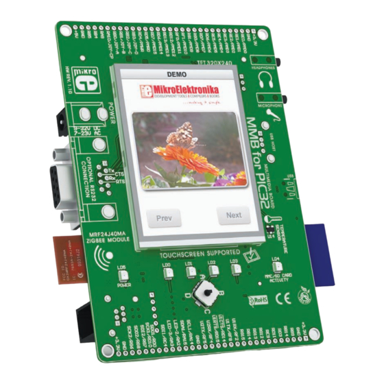
MultiMedia Board
for PIC32MX4
All MikroElektronika´s development systems represent irreplaceable tools for
programming and developing microcontroller-based devices. Carefully chosen
components and the use of machines of the last generation for mounting and
testing thereof are the best guarantee of high reliability of our devices. Due to
simple design, a large number of add-on modules and ready to use examples,
all our users, regardless of their experience, have the possibility to develop
their project in a fast and efficient way.
™
Manual
Advertisement
Table of Contents

Related Manuals for mikroElektronika MultiMedia Board


Summary of Contents for mikroElektronika MultiMedia Board
- Page 1 MultiMedia Board Manual for PIC32MX4 All MikroElektronika´s development systems represent irreplaceable tools for programming and developing microcontroller-based devices. Carefully chosen components and the use of machines of the last generation for mounting and testing thereof are the best guarantee of high reliability of our devices. Due to...
- Page 2 TO OUR VALUED CUSTOMERS I want to express my thanks to you for being interested in our products and for having confidence in mikroElektronika. The primary aim of our company is to design and produce high quality electronic products and to constantly improve the performance thereof in order to better suit your needs.
-
Page 3: Table Of Contents
MultiMedia Board TABLE OF CONTENTS Introduction to MultiMedia Board ...................... 4 Key Features ............................ 5 1.0. Power Supply ..........................6 2.0. PIC32MX4 Microcontroller ......................8 3.0. RS-232 Communication Module ....................9 4.0 Accelerometer ........................... 10 5.0 Temperature Sensor ........................11 6.0. -
Page 4: Introduction To Multimedia Board
The heart of the system is a 32-bit microcontroller PIC32MX4XXL which is programmed by using external programmers ICD2 ® and ICD3 ® from Microchip ® . The MultiMedia Board features many peripheral modules such as ZigBee wireless communication module, RS-232 serial communication module, TFT 320x240 touch screen display, two USB connectors for communication with the microcontroller, temperature sensor, etc. -
Page 5: Key Features
MultiMedia Board Key Features 9. Pads 1. Headphone connector 10. ICD2 and ICD3 programmers connector 2. Microphone connector 11. Optional ZigBee module 3. USB A HOST connector 12. RS-232 communication connector 4. USB MINI-B connector 13. AC/DC connector 5. Temperature sensor 14. -
Page 6: Power Supply
1.0. Power Supply There is an AC/DC connector marked POWER provided on the MultiMedia Board. It enables the board to be interfaced to a power supply source. Plug the appropriate power supply cable connector (A) into the AC/DC connector POWER (B), Figure 1-1. - Page 7 23V) or DC (in the range between 9V and 32V). Upon voltage stabilization, the MCP36063A circuit will provide +5 V on its output. As soon as the power supply voltage is supplied on the DC connector, the MultiMedia Board is ready for use. A USB cable with the appropriate connector is needed for powering the system over a MINI-B type USB connector.
-
Page 8: Pic32Mx4 Microcontroller
Each pad is marked as the pin it is connected to. The advantage of these pads is that they also enable access to the microcontroller pins which are not used by the MultiMedia Board’s modules. Due to it, the 32-bit microcontroller can be used to its full capacity. -
Page 9: Rs-232 Communication Module
RS-232 serial communication is performed through a 9-pin SUB-D connector and the microcontroller’s UART module. The MultiMedia Board provides one single RS-232 port. The microcontroller pins used in such communication are marked as follows: RX - receive data line and TX - transmit data line. Baud rate goes up to 115 kbps. -
Page 10: Accelerometer
4.0. Accelerometer The ADXL345 circuit enables the MultiMedia Board to measure acceleration, space orientation, gravitation etc. One of its main functions here is to determine the orientation of the graphic contents shown on the TFT display. Communication between the ADXL345 circuit and the microcontroller is enabled via a Serial Peripheral Interface (SPI). -
Page 11: Temperature Sensor
MultiMedia Board 5.0. Temperature Sensor Measuring temperature is one of the most commonly performed measurement operations. The MultiMedia Board is capable of measuring temperature within the range of -40 C to +125 C with +/-2 C accuracy by means of the MCP9700A temperature sensor provided on the board. -
Page 12: Zigbee Module
6.0. ZigBee Module The MultiMedia Board keeps side by side to the wireless communication development so that it provides an interface to the ZigBee module. The operation of the ZigBee module is based on the IEEE 802.15.4-2003 standard which relates to wireless data transfer on short distances with low-power consumption. -
Page 13: Joystick
A joystick is a movable stick that can be moved in several directions. Every movement can be registered by the software. The MultiMedia Board provides a joystick used as a push-button. Its function is determined in the program, written by the user, and loaded into the microcontroller. -
Page 14: Touch Screen
8.0. Touch Screen The MultiMedia Board features a 320x240 resolution TFT display covered with a touch panel sensitive to touch. The display is capable of showing 262.000 different colors. The TFT display and touch panel together form a functional unit called a touch screen. The touch screen can be used to show images, videos and other graphic content, menu navigation etc. -
Page 15: Flash Memory
MultiMedia Board 9.0. Flash Memory Since multimedia applications are getting increasingly demanding, it is necessary to provide additional memory space that the microcontroller can use to store programs. The M25P80 circuit enables the microcontroller to use additional 8Mbit flash memory. -
Page 16: Serial Eeprom Module
MultiMedia Board 10.0. Serial EEPROM Module EEPROM (Electrically Erasable Programmable Read-Only Memory) is a built-in memory module used to store data that must be saved when the power goes off. The 24AA01 circuit is capable of storing up to 1Kbit data and uses serial I C communication to exchange data with the microcontroller via its pins RA14 and RA15. -
Page 17: Mmc/Sd Connector
11.0. MMC/SD Connector There is a built-in MMC/SD connector used to insert MMC/SD card provided on the MultiMedia Board. It enables the system to additionally expand memory space. SPI interface is used for communication between the microcontroller and MMC/SD card, whereas a LED marked MMC/SD CARD ACTIVITY (LD4) indicates data transfer between them. -
Page 18: Leds
The MultiMedia Board uses LEDs with current I=1mA. There are four LEDs provided on the MultiMedia Board that can be assigned a signal function. They are connected to the following I/O microcontroller pins: LD0 - RA0, LD1 - RA1, LD2 - RA2 and LD3 - RA3. A LED marked POWER is used to indicate that the system is turned on, whereas a diode marked MMC/SD indicates memory card activity. -
Page 19: Microphone Input
MultiMedia Board 13.0. Microphone Input A microphone can be interfaced to the system via a 3.5mm connector CN7 and the WM8731SEDS circuit. This circuit is a stereo CODEC with an integrated headphones driver. Its function is to convert an analog signal from interfaced microphone to a digital value, then to transfer it to the microcontroller or as a sidetone to the headphones output. -
Page 20: Audio Output
14.0. Audio Output The MultiMedia Board is also able to generate an audio signal using WM8731SEDS or MCP6022 circuits. The WM8731SEDS is used to convert digital data from the microcontroller to audio signal to be transferred to headphones. Communication between this circuit and the microcontroller is performed via a Serial Peripheral Interface (SPI). -
Page 21: Usb Connectors
15.0. USB Connectors There are two USB connectors provided on the MultiMedia Board. One is a MINI-B type USB connector which is used for connection with a PC, whereas the other is an A type USB connector which serves as a USB HOST connector. The latter enables peripheral devices, such as printer, to be connected to the system. -
Page 22: Icd Programmer
The microcontroller provided on the MultiMedia Board can be programmed using either ICD2 or ICD3 programmer from Microchip. When using these programmers, it is necessary to provide the MultiMedia Board with the power supply voltage first. If the system is powered via the ICD2 or ICD3 programmer, it is crucial to activate the appropriate option within the MPLAB program. - Page 23 MikroElektronika has been advised of the possibility of such damages. MikroElektronika reserves the right to change information contained in this manual at any time without prior notice, if necessary.
- Page 25 Mouser Electronics Authorized Distributor Click to View Pricing, Inventory, Delivery & Lifecycle Information: mikroElektronika MIKROE-433...
Need help?
Do you have a question about the MultiMedia Board and is the answer not in the manual?
Questions and answers