Table of Contents
Advertisement
Quick Links
Installation Instructions
Original Instructions
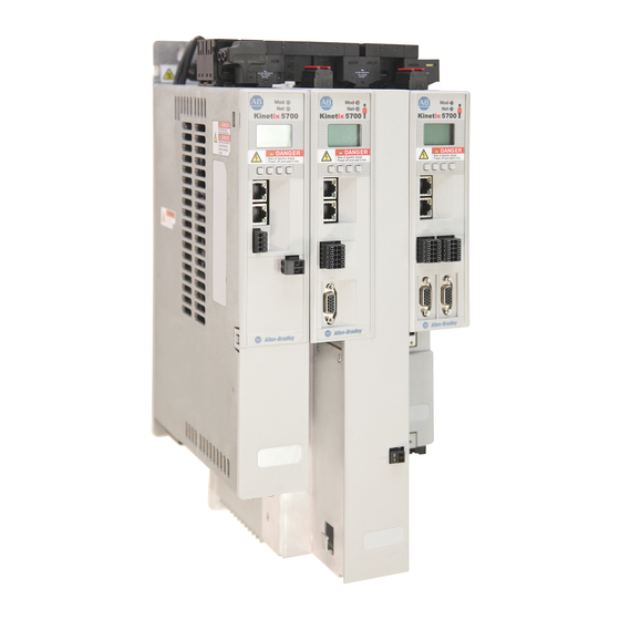
Kinetix 5700 Regenerative Bus Supply
Catalog Numbers 2198-RP088, 2198-RP200, 2198-RP263, 2198-RP312
Topic
About the Regenerative Bus Supply
The Kinetix® 5700 regenerative bus supply with 400V-class three-phase AC input provides
continuous output power and current to servo drives for applications with requirements in the
range of 24...140 kW and 35...207 A, respectively.
See the Kinetix 5700 Servo Drives User Manual, publication 2198-UM002, for detailed
information on wiring, applying power, troubleshooting, and integration with
ControlLogix® 5580 controllers with EtherNet/IP communication modules or
CompactLogix™ 5380 controllers with embedded EtherNet/IP network connections.
Page
1
2
2
3
3
6
7
8
11
14
16
18
19
Advertisement
Table of Contents


Need help?
Do you have a question about the Kinetix 5700 Series and is the answer not in the manual?
Questions and answers