Table of Contents
Advertisement
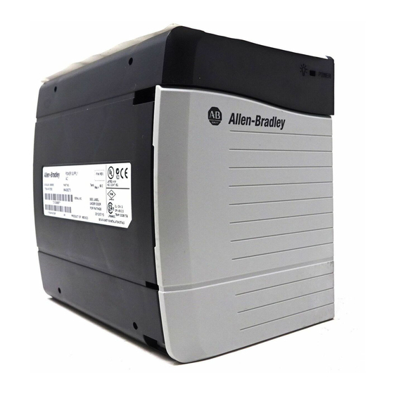
ControlLogix Power Supplies
Catalog Numbers 1756-PA75/B, 1756-PB75/B
Use this publication when installing the ControlLogix™ power supplies.
For more information on:
You mount a non-redundant power supply directly on the left end of the
ControlLogix chassis, where it plugs directly into the backplane. The power supply
provides power for all modules installed in the chassis.
Installation Instructions
See page:
3
3
5
7
7
9
10
11
12
12
13
14
15
Advertisement
Table of Contents


Need help?
Do you have a question about the ControlLogix 1756-PA75/B and is the answer not in the manual?
Questions and answers