Advertisement
Quick Links
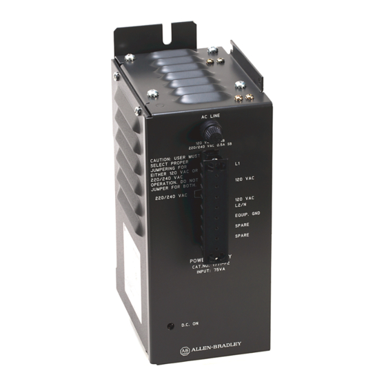
(Cat. No. 1771-P2)
Installation Data
This document provides information on:
preparing to install the power supply
installing the power supply
connecting ac power to the power supply
power supply output
troubleshooting
specifications
The auxiliary power supply can power one bulletin 1771 I/O chassis
when used with an adapter module, a 1772 Mini-PLC-2 processor, or a
1772 Mini-PLC-2/15 processor.
The auxiliary power supply does not provide battery backup. For battery
backup, use a system power supply (cat. no. 1771-P1).
If you mount the power supply on the left side-plate of the I/O chassis,
mount the I/O chassis first (if you have not already done so). See the
Universal I/O Chassis Installation Data (publication 1771-2.210) for
information on mounting the I/O chassis.
When mounted separately, the power supply can be mounted above or next
to the I/O chassis. It can not be mounted below since it is necessary to
allow convection cooling of both the power supply and the I/O chassis.
A minimum vertical distance of six inches should be maintained.
Advertisement

Related Manuals for Allen-Bradley 1771-P2


Summary of Contents for Allen-Bradley 1771-P2
- Page 1 (Cat. No. 1771-P2) Installation Data This document provides information on: preparing to install the power supply installing the power supply connecting ac power to the power supply power supply output troubleshooting specifications The auxiliary power supply can power one bulletin 1771 I/O chassis when used with an adapter module, a 1772 Mini-PLC-2 processor, or a 1772 Mini-PLC-2/15 processor.
- Page 2 ATTENTION: If you do not remove system power, you could damage the module circuitry and/or cause undesired operation with possible injury to personnel. Remove system power. Mount the power supply.
- Page 3 To connect backplane power: Connect one 9-pin plug of the power cable to the 9-pin connector located on the bottom of the power supply. Connect the other 9-pin plug to the external power supply connector on the I/O chassis. To make this connection, remove the processor/adapter module and left-most I/O module from the I/O chassis.
- Page 4 220/240V operation, remove the 1A fuse and replace it with the 0.5A slow-blow fuse that is provided. Replacement fuses are shown below: A replacement fuse kit (cat. no. 1771-FP) containing both 1A and 0.5A fuses is available. Contact your local Allen-Bradley representative for further information.
- Page 5 The power supply monitors input voltage for proper operating levels. AC input line connections for either 120V ac or 220/240V ac are made to the terminals marked L1 and L2. Use the grounding stud located on the bottom of the power supply to connect the power supply to the system ground bus.
- Page 6 The power supply has a D.C. ON LED indicator that provides status indication during power supply operation. For additional assistance, contact your local Allen-Bradley representative.
- Page 7 Use these graphs to determine your: cooling requirements power cost transformer size (unless the transformer manufacturer has a recommended multiplier for sizing a transformer for an ac-to-dc power supply) PLC-2 and PLC-2/15 are registered trademarks of Allen-Bradley Company, Inc.
- Page 8 As a subsidiary of Rockwell International, one of the world’s largest technology companies — Allen-Bradley meets today’s challenges of industrial automation with over 85 years of practical plant-floor experience. More than 11,000 employees throughout the world design, manufacture and apply a wide range of control and automation products and supporting services to help our customers continuously improve quality, productivity and time to market.
Need help?
Do you have a question about the 1771-P2 and is the answer not in the manual?
Questions and answers