Table of Contents
Advertisement
Quick Links
Advertisement
Table of Contents

Related Manuals for DFI VC70B-KU


Summary of Contents for DFI VC70B-KU
- Page 1 VC70B-KU User’s Manual A52700931 Chapter 1 Introduction www.dfi.com...
-
Page 2: Copyright
Product names or trademarks appearing in this manual are for identification purpose only and ance could void the user’s authority to operate the equipment. are the properties of the respective owners. Shielded interface cables must be used in order to comply with the emission limits. Chapter 1 Introduction www.dfi.com... -
Page 3: Table Of Contents
Boot ................................42 Exit ................................43 Specifications ......................7 Chapter 8 - Supported Software ........... 45 Getting to Know the VC70B-KU ................8 Chapter 9 - Intel AMT Settings ..........52 Mechanical Dimensions ..................9 Chapter 2 - Getting Started ............. 10 Chapter 3 - Installing the Devices......... -
Page 4: About This Manual
After installation or servicing, cover the system chassis before plugging the power cord. Battery: • Danger of explosion if battery incorrectly replaced. • Replace only with the same or equivalent type recommend by the manufacturer. • Dispose of used batteries according to local ordinance. Chapter 1 Introduction www.dfi.com... -
Page 5: Safety Precautions
• Unplug the power cord before removing the system chassis cover for installation or servic- ing. After installation or servicing, cover the system chassis before plugging the power cord. • 1 VC70B-KU system unit • Mounting screws for M.2 and Mini PCIe modules •... -
Page 6: Chapter 1 - Introduction
Chapter 1 Chapter 1 - Introduction Key Features Overview Model Name VC70B-KU Processor ® 7th Generation Intel Core processors, BGA 1356 Two LAN ports Six COM ports Display VGA & HDMI Audio Microphone and Line-out Four USB 3.0 & two USB 2.0 Type A ports... -
Page 7: Specifications
- Status LED Vibration: - HDD LED - VGA Port MIL-STD 810G 514.6C-3 - Five (two support RS232/422/485; two support only RS232; one Certifications: supports RS232 or 8-bit DIO or CAN bus) CE, FCC Class A, RoHS Chapter 1 Introduction www.dfi.com... -
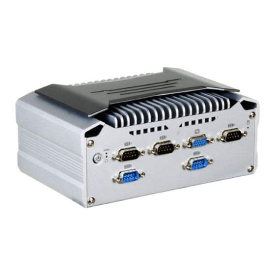
Page 8: Getting To Know The Vc70B-Ku
Getting to Know the VC70B-KU Front View USB 3.0 USB 3.0 Status LED COM 3 (blue) LAN 2 LAN 1 Line-out Mic-in HDMI COM 2 COM 1 COM 4/ 8-bit DIO Power Button with LED (green) HDD LED Reset DC-in USB 2.0... -
Page 9: Mechanical Dimensions
Chapter 1 Mechanical Dimensions Chassis Dimensions Motherboard Dimensions 184.00 82.00 115.00 103.20 98.20 Left View Right View 18.00 8.00 0.00 Chapter 1 Introduction www.dfi.com... -
Page 10: Chapter 2 - Getting Started
Installing the Drivers The system package includes a CD disk. The CD includes drivers that must be installed to pro- vide the best system performance. Refer to the Supported Software chapter for instructions on installing the drivers. Chapter 2 Getting Started www.dfi.com... -
Page 11: Chapter 3 - Installing The Devices
2. Place the SATA drive bay with the installed HDD back to the system and connect the SATA cable to the SATA connectors on the system board. SATA power connector SATA mounting place SATA data connector Power board SATA cable Mounting screw Mounting screw Chapter 3 Installing the Devices www.dfi.com... -
Page 12: Installing A Mini Pcie Card
Refer to jumper settings for signal selection for this slot. from the main board The power board connects to the mainboard with a 4-pin power cable, please reconnect this cable if it is removed during installation. Screw Chapter 3 Installing the Devices www.dfi.com... - Page 13 COM 4 as a CANbus port. For pin assignments of this port, refer to Chapter 5 ̶ Ports and Connectors. To switch signals for COM 4, refer to Chapter 4 ̶ Jumper Settings. JP1/JP2 Mounting screw CANbus card Chapter 3 Installing the Devices www.dfi.com...
-
Page 14: Chapter 4 - Jumper Settings
2. Set jumper pins 2 and 3 to On. Wait for a few seconds and set the jumper back to its de- fault setting, pins 1 and 2 On. 3. Now plug the power cord and power on the system. Chapter 4 Jumper Settings www.dfi.com... -
Page 15: Mini Pcie/Sata Signal Select
The system board uses JP1 and JP2 to select between RS232 serial communication or 8-bit digital I/O for the DB-9 connector (COM 4) on the front panel. Important: You cannot use COM 4 and DIO at the same time. Please set JP1 and JP2 together. Chapter 4 Jumper Settings www.dfi.com... -
Page 16: Chapter 5 - Ports And Connectors
- COM 4 can be an RS232, an 8-bit DIO or a CANbus port • One serial COM port: - COM 5 & COM 6 are RS232 ports - COM 3 is an RS232 port Chapter 2 Hardware Installation Chapter 5 Ports and Connectors www.dfi.com... -
Page 17: Display Interfaces
HDMI Port The HDMI port, which carries both digital audio and video signals, is used to connect the HDMI port of an LCD monitor or a digital TV. Chapter 2 Hardware Installation Chapter 5 Ports and Connectors www.dfi.com... -
Page 18: Usb Ports
The system board is equipped with four onboard USB 3.0 ports (USB 1-4). USB devices allow data exchange between your computer and a wide range of simultaneously accessible external Plug and Play peripherals. Chapter 2 Hardware Installation Chapter 5 Ports and Connectors www.dfi.com... -
Page 19: Com (Serial) Ports
DIO5 BIOS Setting DIO6 Configure the serial ports including the communication mode in the “Advanced” menu (Super DIO7 I/O submenu) of the BIOS. Refer to Chapter 7 for more information. Chapter 2 Hardware Installation Chapter 5 Ports and Connectors www.dfi.com... -
Page 20: Rj45 Lan Ports
Install the audio driver. Refer to the Chapter 8 for more information. Blinking Data Activity Green 100Mbps connection Link Orange 1Gbps connection Driver Installation Install the LAN drivers. Refer to Chapter 8 for more information. Chapter 2 Hardware Installation Chapter 5 Ports and Connectors www.dfi.com... -
Page 21: I/O Connectors
Chapter 7 for the designated SATA port of this slot. BIOS Setting Configure the Serial ATA drives in the Advanced menu (“SATA Configuration” submenu) of the BIOS. Refer to Chapter 7 for more information. Chapter 2 Hardware Installation Chapter 5 Ports and Connectors www.dfi.com... -
Page 22: Front Panel Connector
PWR_BTN SUS_LED RESET_BTN HDD_LED Pin Pin Assignment Pin Pin Assignment HDD Power Power Button PWR_BTN HDD_LED Ground Ground Ground Power LED PWR_LED RESET_BTN RST Signal Ground Ground SUS_LED SUS LED Chapter 2 Hardware Installation Chapter 5 Ports and Connectors www.dfi.com... -
Page 23: Standby Power Led
• Danger of explosion if battery incorrectly replaced. • Replace only with the same or equivalent type recommend by the manufacturer. • Dispose of used batteries according to local ordinance. Chapter 2 Hardware Installation Chapter 5 Ports and Connectors www.dfi.com... - Page 24 Please make sure that system-off delay time is sufficient to allow the OS to shut nition on/off and system on/off delay time control; please refer to the table on the right for down completely. more information. Chapter 2 Hardware Installation Chapter 5 Ports and Connectors www.dfi.com...
-
Page 25: Chapter 6 - Mounting Options
Chapter 6 Chapter 6 - Mounting Options Use the provided mounting screws to attach the wall mount brackets to both sides on the bottom of the system. Wall Mount The wall mount kit includes the following: Mounting screw • 2 Wall mount brackets •... - Page 26 Chapter 6 VESA Mount Attach the VESA mount bracket A to the back of your display using four screws as shown in the picture below. Note: The system unit used in the following illustrations may not resemble the actual one. These illustrations are for reference only.
- Page 27 Chapter 6 DIN Rail Mount Align the mounting holes on the system and the mounting holes on the bracket, and then use the screws removed in step 1 to secure the bracket in place. Note: 3. The 3 mounting holes on the bracket are used to affix the DIN-rail mount clip to the The system unit used in the following illustrations may not resemble the actual one.
-
Page 28: Chapter 7 - Bios Setup
“Press DEL to run setup” will appear on the screen. If the message disappears before you respond, restart the system or press the “Reset” button. You may also restart the system by pressing the <Ctrl> <Alt> and <Del> keys simultaneously. Chapter 7 BIOS Setup www.dfi.com... -
Page 29: Main
23. Minute displays minutes from 00 to 59. Second displays seconds from 00 to 59. System Date The date format is <month>, <date>, <year>. Month displays the month, from Janu- ary to December. Date displays the date, from 1 to 31. Year displays the year, from 1980 to 2099. Chapter 7 BIOS Setup www.dfi.com... - Page 30 Note that this configuration is only shown when the “Boot Type” is set to “Legacy Boot advantageous to the overall system performance. Type” or “Dual”. Select the combination of the display at boot: Auto, HDMI+VGA or VGA+HDMI. Chapter 7 BIOS Setup www.dfi.com...
- Page 31 Select Serial ATA device speed: Gen1 (1.5 Gbit/s), Gen2 (3 Gbit/s), Gen 3 (6 Gbit/s) or High-definition audio devices will be unconditionally disabled. auto. Enabled High-definition audio devices will be unconditionally enabled. Auto High-definition audio devices will be enabled if present and disabled otherwise. Chapter 7 BIOS Setup www.dfi.com...
- Page 32 SATA Port 0: Controls the SATA signal of the SATA port on the system board. ownership change will be claimed by the XHCI driver. SATA Port 1: Controls the SATA signal of the half-size mini PCIe slot. Chapter 7 BIOS Setup www.dfi.com...
- Page 33 Controls the PCIe signal of the full-size Mini PCIe slot. or Gen3 (8 GT/s). Mini PCIe Slot-2 (half) Hot Plug Controls the PCIe signal of the half-size Mini PCIe slot. Enable or disable the hot plug function of each serial ATA port. Chapter 7 BIOS Setup www.dfi.com...
- Page 34 Enable or disable flashing of the Intel Management Engine (ME) region. ® Enable or disable Intel Active Management Technology BIOS extension. ® Un-Configure ME Clears all ME related configurations without requiring a password on the next boot. Chapter 7 BIOS Setup www.dfi.com...
-
Page 35: Uefi Device Manager
When this function is selected, the screen will warn you that you are going to exit the BIOS setup utility. Dynamic EFI Debug Enable or disable output of the debugging messages through a serial port. Chapter 7 BIOS Setup www.dfi.com... - Page 36 “Device list”. Select “Network Device List” to view all of the detected network devic- es. For each network device, you can select to view and configure its settings. In addition, you can select either the IPv4 or IPv6 network settings for UEFI network configuration. Chapter 7 BIOS Setup www.dfi.com...
- Page 37 . x . x . x (x must be a decimal value between 0 and 255). Local Gateway: Enter the gateway address in the IPv4 format. Local DNS (Domain Name System) Servers: Enter DNS (Domain Name System) server IP addresses in the IPv4 format. Chapter 7 BIOS Setup www.dfi.com...
- Page 38 1, the system or CPU fan should be turned on and operate at the designated speed. The range of the temperature is from 0 to 127 Fan Speed Count 1 to Fan Speed Count 4 Set the fan speed. The range is from 1 (lowest speed)-100% (full speed). Chapter 7 BIOS Setup www.dfi.com...
- Page 39 This section displays PC health status. Enable or disable the watchdog function. A counter will appear if you select to enable WDT. Input any value between 1 and 255. Case Open Enable or disable the case open function. Chapter 7 BIOS Setup www.dfi.com...
- Page 40 Parity: None, Even or Odd. Stop bits: 1 bit or 2 bits. Flow control: None, RTS/CTS or XON/XOFF This is the global setting for all of the designated serial ports for the console redirec- tion function. Chapter 7 BIOS Setup www.dfi.com...
-
Page 41: Security
If you select to set the supervisor password, this option will be shown. Enable or disable the system to require password at boot. • Disable: Disable and deactivate TPM. • Enable: Enable and activate TPM. Clear TPM Remove all TPM ownership contents. Chapter 7 BIOS Setup www.dfi.com... -
Page 42: Boot
Windows 8 BitLocker Network Unlock, UEFI IPv4/IPv6 PXE and legacy PXE option ROM. PXE Boot to LAN (Legacy Boot Type)/PXE Boot Capability (Dual Boot Type) Enable or disable Preboot eXecution Environment (PXE) boot to LAN. USB Boot Enable or disable booting to USB boot devices. Chapter 7 BIOS Setup www.dfi.com... -
Page 43: Exit
DSF file extension and can be used for restoration. Restore Setting from file Select this option to restore BIOS configuration settings from a USB drive. Note that this option will not be available if there aren’t any USB devices detected on the system. Chapter 7 BIOS Setup www.dfi.com... - Page 44 Knowledge/Video/31 from the Knowledge Base of the DFI website. 2. The BIOS (SPI ROM) on this system board must be the original equipment from the factory and cannot be used to replace one which has been utilized on other system boards.
-
Page 45: Chapter 8 - Supported Software
Chapter 8 - Supported Software The system requires you to install drivers for some devices to operate properly. To download the latest driver, please go to the DFI Download Center: http://www.dfi.com/DownloadCenter Once you are in the Download Center page, select your product or type the model name and click "Search"... - Page 46 Click “Next”. 4. Please wait while the instal- lation is in progress. 2. Read the license agreement, and then click “Yes”. 5. Click “Restart Now” to allow the new software installa- tion to take effect. Chapter 8 Supported Software www.dfi.com...
- Page 47 2. Read the license agree- 5. Click “Yes, I want to restart ment, and then click “Yes”. this computer now”, and then click “Finish”. Restarting the system will allow the new software installation to take effect. Chapter 8 Supported Software www.dfi.com...
- Page 48 “Finish”. 2. Click “I accept the terms in the license agreement” if you accept the agreement, and then click “Next”. 3. Select the program features you want to install, and then click “Next”. Chapter 8 Supported Software www.dfi.com...
- Page 49 1. You are about to install the driver. Click “Next” to continue. 4. Please wait while the prod- uct is being installed. 2. Read the license agree- ment, and then click “Next”. 5. After the installation is complete, click “Finish”. Chapter 8 Supported Software www.dfi.com...
- Page 50 Click “I accept the terms in the “Finish”. License Agreement” if you agree with the terms in the agreement and then Restart the system to allow the new click “Next”. software installation to take effect. Chapter 8 Supported Software www.dfi.com...
- Page 51 5. Setup is now installing the driver. 3. Read the file information and then click “Next”. 4. Setup is ready to install the driver. 6. Click “Finish” to exit the setup. Click “Next” to begin the installation. Chapter 8 Supported Software www.dfi.com...
-
Page 52: Chapter 9 - Intel Amt Settings
It protects the network from threats at the source by proactively blocking incoming threats, reactively containing infected clients before they impact the network, and proactively alerting when critical software agents are removed. 3. In the “Active Management Technology Support” menu, select “Enabled” for “Intel AMT Support”. Chapter 9 Intel AMT Settings www.dfi.com... - Page 53 Copyright(C) 2003-16 Intel Corporation. All Rights Reserved MAIN MENU MEBx Login > Intel (R) ME General Settings > Intel (R) AMT Configuration MEBx Exit Intel(R) ME Password [↑↓] = Move Highlight [Enter] = Select Entry [Esc]= Exit Chapter 9 Intel AMT Settings www.dfi.com...
- Page 54 Intel(R) Management Engine BIOS Extension v11.0.0.0008/Intel(R) ME v11.8.50.3399 Copyright(C) 2003-16 Intel Corporation. All Rights Reserved MAIN MENU > Intel (R) ME General Settings > Intel (R) AMT Configuration MEBx Exit [↑↓] = Move Highlight [Enter] = Select Entry [Esc]= Exit Chapter 9 Intel AMT Settings www.dfi.com...
- Page 55 > User Consent Password Policy <Anytime> > Network Setup Activate Network Access Unconfigure Network Access <Full Unprovision> > Remote Setup And Configuration > Power Control [↑↓] = Move Highlight [Enter] = Select Entry [Esc]= Exit Chapter 9 Intel AMT Settings www.dfi.com...
- Page 56 <Full Unprovi- Disabled sion> Enabled > Remote Setup And Configuration > Power Control [↑↓] = Move Highlight [Enter] = Select Entry [Esc]= Exit [↑↓] = Move Highlight [Enter] = Complete Entry [Esc]= Discard Changes Chapter 9 Intel AMT Settings www.dfi.com...
- Page 57 < Enabled> Storage Redirection <Enabled> KVM Feature Selection <Enabled> NONE Disabled Enabled [↑↓] = Move Highlight [Enter] = Complete Entry [Esc]= Discard Changes [↑↓] = Move Highlight [Enter] = Complete Entry [Esc]= Discard Changes Chapter 9 Intel AMT Settings www.dfi.com...
- Page 58 > Remote Setup And Configuration > Power Control Default Password Only During Stepup And Configuration Anytime [↑↓] = Move Highlight [Enter] = Select Entry [Esc]= Exit [↑↓] = Move Highlight [Enter] = Complete Entry [Esc]= Discard Changes Chapter 9 Intel AMT Settings www.dfi.com...
- Page 59 Shared/ Dedicated FQDN <Shared> Dynamic DNS Update <Disabled> Dynamic DNS Update <Disabled> Computer Domain Name Disabled Enabled [Enter] = Complete Entry [Esc]= Discard Changes [↑↓] = Move Highlight [Enter] = Complete Entry [Esc]= Discard Changes Chapter 9 Intel AMT Settings www.dfi.com...
- Page 60 Unconfigure Network Access > Remote Setup And Configuration Full Unprovision > Power Control [↑↓] = Move Highlight [Enter] = Complete Entry [Esc]= Discard Changes [↑↓] = Move Highlight [Enter] = Complete Entry [Esc]= Discard Changes Chapter 9 Intel AMT Settings www.dfi.com...
- Page 61 > RCFG > TLS PKI > TLS PKI Provisioning Mode: PKI Provisioning server address [↑↓] = Move Highlight [Enter] = Select Entry [Esc]= Exit [↑↓] = Move Highlight [Enter] = Select Entry [Esc]= Exit Chapter 9 Intel AMT Settings www.dfi.com...
- Page 62 PKI DNS Suffix > Manage Hashes This will activate Remote Condigura- tion. Continue: (Y/N) Disabled Enabled [↑↓] = Move Highlight [Enter] = Select Entry [Esc]= Exit [↑↓] = Move Highlight [Enter] = Select Entry [Esc]= Exit Chapter 9 Intel AMT Settings www.dfi.com...
- Page 63 Activate Network Access Unconfigure Network Access <Full Unprovision> > Remote Setup And Configuration > Power Control [↑↓] = Move Highlight [Enter] = Select Entry [Esc]= Exit [↑↓] = Move Highlight [Enter] = Select Entry [Esc]= Exit Chapter 9 Intel AMT Settings www.dfi.com...
- Page 64 This configurations are effective only after AMT provisioning has started Intel (R) ME ON in Host Sleep States <Mobile: ON in S0, ME Wake in S3, S4-5 (AC only)> Idle Timeout 65535 Timeout Value (1-65535) 65535 <ENTER> = Complete Entry [ESC]= Discard Changes Chapter 9 Intel AMT Settings www.dfi.com...
Need help?
Do you have a question about the VC70B-KU and is the answer not in the manual?
Questions and answers