
Subscribe to Our Youtube Channel
Related Manuals for Winmate Military M270TF-MIL


Summary of Contents for Winmate Military M270TF-MIL
-
Page 1: User Manual
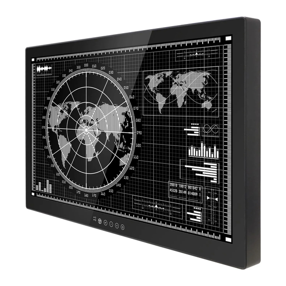
4K UHD Display Military Grade M270TF-MIL Model No: M320TF-MIL User Manual Version 1.0 Document Part Number: 91521110100K... -
Page 2: Copyright Notice
Preface Copyright Notice No part of this document may be reproduced, copied, translated, or transmitted in any form or by any means, electronic or mechanical, for any purpose, without the prior written permission of the original manufacturer. Trademark Acknowledgement Brand and product names are trademarks or registered trademarks of their respective owners. -
Page 3: Customer Service
Customer Service We provide a service guide for any problem by the following steps: First, visit the website of our distributor to find the update information about the product. Second, contact with your distributor, sales representative, or our customer service center for technical support if you need additional assistance. - Page 4 Advisory Conventions Four types of advisories are used throughout the user manual to provide helpful information or to alert you to the potential for hardware damage or personal injury. These are Notes, Important, Cautions, and Warnings. The following is an example of each type of advisory. NOTE: A note is used to emphasize helpful information IMPORTANT:...
-
Page 5: Safety Precautions
Safety Precautions For your safety carefully read all the safety instructions before using the device. All cautions and warnings on the equipment should be noted. Keep this user manual for future reference. On Safety • M270TF-XXX / M320TF-XXX is a DC powered device. Use with the supplied AC adaptor (AC-300MD). -
Page 6: About The Lcd Display Panel
On Installation • Prevent internal heat build-up allowing adequate air circulation. • Do not place the unit on surfaces (rugs, blankets, etc.) or near materials (curtains, draperies) that may block the ventilation holes. • Do not install the unit near heat sources such as radiators or air ducts, or in a place subject to direct sunlight, excessive dust, mechanical vibration or shock. - Page 7 CAUTION! POSSIBLE PROBLEM PREVENTION Sunlight shines directly will You should avoid placing the cause the panel damage. product under direct sunlight. Do not expose the display to direct sunlight. If the product is close to the You should avoid placing the wet ground such as product in wet grassplot, the moisture...
-
Page 8: Important Safety Information
Important Safety Information Countries/ Symbol This equipment complies with essential requirements of: Area Electromagnetic Compatibility Directive(2014/30/EU) Low Voltage Directive (2014/35/EU) Restrictions of the use of certain hazardous substances European (RoHS) Directive (2011/65/EU) Union FCC Part 15 Subpart B Regulations Class B Federal Communications Commission Radio Frequency Interface Statement This device complies with part 15 FCC rules. - Page 9 European Union Thus equipment is in conformity with the requirement of the following EU legislations and harmonized standards. Product also complies with the Council directions. Electromagnetic Compatibility Directive (2014/30/EU) EN55024: 2010 EN 55022: 2010 Class B o IEC61000-4-2: 2009 o IEC61000-4-3: 2006+A1: 2007+A2: 2010 o IEC61000-4-4: 2012 o IEC61000-4-5: 2014...
-
Page 10: About This User Manual
About This User Manual This User Manual provides information about using the Winmate® Military Grade 4K UHD Display. The documentation set for the Military Grade 4K UHD Display provides information for specific user needs, and includes: Military Grade 4K UHD Display User Manual – contains detailed description on how to use the device, its components and features. -
Page 11: Table Of Contents
Contents Preface ............................ii About This User Manual ....................... x 1 Introduction ..........................15 1.1 Product Features ........................ 15 1.2 Hardware Specifications ....................16 1.3 Package Contents ....................... 18 1.4 Schematics and Dimensions ....................19 1.4.2 Model 27” ....................... 19 1.4.3 Model 32”... - Page 12 4.4.2 Display ........................40 4.4.3 Adjust ........................41 4.4.4 Audio ........................42 4.4.5 Multi-display Settings ....................43 4.4.6 OSD Setting ......................44 4.4.7 Advanced ......................... 45 5 Maintenance ........................... 47 5.1 Cleaning the Display Screen ....................47 5.2 Cleaning the Casing ......................48 6 Technical Support ........................
- Page 13 Introduction This chapter gives you product overview, describes features and hardware specification. You will find all accessories that come with the Display in the packing list. Military 4K UHD Display...
-
Page 15: Introduction
2160) native resolution help to minimize errors and improve operational efficiencies. With the number of display options available, knowing which will best suit your needs can be a challenge. The Winmate line of 4K monitors, implement the latest in technology, are making the decision easy. -
Page 16: Hardware Specifications
User Manual Chapter 1 Introduction 1.2 Hardware Specifications Display Specifications Model Name M270TF-MIL M320TF-MIL Display TFT Technology LED Backlight Technology, TFT Active-matrix, Widescreen, IPS Technology Viewable Size 27” diagonal 32” diagonal Active Area 596.16”(H ) x 335.34”(V ) mm 708.48”(H ) x 398.52”(V ) mm Native Resolution 3840 x 2160 (UHD 4K) 3840 x 2160 (UHD 4K) - Page 17 User Manual Chapter 1 Introduction Mechanical Specifications Dimensions 643.17 x 408.06 x 48 mm 777.58 x 477.62 x 48 mm Mounting VESA mounting 100 x 100mm VESA mounting 100 x 100mm VESA mounting 200 x 100mm VESA mounting 200 x 100mm VESA mounting 300 x 100mm Product Weight 9.0 Kg...
-
Page 18: Package Contents
User Manual Chapter 1 Introduction 1.3 Package Contents Carefully remove the box and unpack your device. Please check if all the items listed below are inside your package. If any of these items are missing or damaged contact us immediately. Standard factory shipment list VESA Mounting Screws Display... -
Page 19: Schematics And Dimensions
User Manual Chapter 1 Introduction 1.4 Schematics and Dimensions This section includes mechanical drawing and mechanical dimensions of the Display. 1.4.2 Model 27” Unit : mm Military 4K UHD Display... -
Page 20: Model 32
User Manual Chapter 1 Introduction 1.4.3 Model 32” Unit : mm Military 4K UHD Display... -
Page 21: I/O Layout
User Manual Chapter 1 Introduction 1.5 I/O Layout This section includes appearance and input/ output connectors’ layout. Description Description ① 24V DC In ⑥ VGA Connector ② DVI Connector ⑦ Audio Line In ③ HDMI 1.4 ⑧ RS-232 for Remote Control ④... -
Page 22: Osd Panel
User Manual Chapter 1 Introduction 1.6 OSD Panel When the enter key is touched, the OSD (On Screen Display) menu will appear on the monitor screen. This menu offers the user ability to make many changes to the image. The table below shows the response after touching the different OSD icons. Icon OSD Menu Status Response... -
Page 23: Soft Power On And Off
User Manual Chapter 1 Introduction 1.7 Soft Power On and Off This table shows the LED light combinations and their meaning: Blue Amber Description Power off Power on activate Searching mode, standby mode Military 4K UHD Display... - Page 24 User Manual Chapter 2 Getting Started Getting Started This chapter tells you important information on power supply, adapter and precautions tips. Pay attention to power considerations. Military 4K UHD Display...
-
Page 25: Getting Started
User Manual Chapter 2 Getting Started 2 Getting Started This chapter provides information on how to connect the device to the source of power, connector pinouts and the guideline to turn on/off the Display. 2.1 Powering On 2.1.1 Power Considerations Follow the recommendations below when powering on the equipment. -
Page 26: Connecting The Power
User Manual Chapter 2 Getting Started 2.1.2 Connecting the Power Follow instructions in this section to connect the display to the source of power. 2.1.2.1 AC Adaptor Components Item Part Description Function Glows green: when the AC adaptor power is On. MAIN POWER indicator OFF: when the AC adaptor power is Off. - Page 27 User Manual Chapter 2 Getting Started 2.1.2.2 Connecting the Power WARNING!/ AVERTISSEMENT! Serious injury due to shock is possible if unit is wired incorrectly or connected to voltage exceeding the input voltage range. Des blessures graves en raison du choc est possible si l'unité est mal câblé ou connecté...
-
Page 28: Connecting Other Devices
User Manual Chapter 2 Getting Started 2.2 Connecting Other Devices This section describes how to connect other devices to 4K UHD Military Display and introduces connector pin assignment. 2.2.1 Removing the Connector Cover To access the connectors, remove the connector cover. Before removing the connector cover, disconnect the power cord. -
Page 29: Connector Pin Assignment
User Manual Chapter 2 Getting Started 2.2.2 Connector Pin Assignment The location and pin assignment of the cables are as follows. There are several video and/or data cables that can be connected in any combination. The number and type of connections will be automatically detected by the monitor. From the OSD (On Screen Display) the user can select the manner in which the images will be displayed. - Page 30 User Manual Chapter 2 Getting Started 2.2.2 DVI Connector Use DVI to connector in the rear of PC system, and plug the other end to the TFT LCD display. Fasten cable connectors with screws. Pin № Signal Name Pin № Signal Name DVI_RX2- DVI_RX2+...
- Page 31 User Manual Chapter 2 Getting Started 2.2.3 HDMI 2.0 Connector Use HDMI to connector in the rear of PC system, and plug the other end to the TFT LCD display. Fasten cable connectors with screws Pin № Signal Name Pin № Signal Name HDMI_RX2+ HDMI_RX2-...
- Page 32 User Manual Chapter 2 Getting Started 2.2.6 VGA Connector Military 4K UHD has VGA connector (D-Sub 15pin Female). Use VGA cable to connect the display to the PC system. Fasten cable connectors with screws. Pin № Signal Name Pin № Signal Name GREEN BLUE...
- Page 33 Mounting Solutions This chapter provides mounting guide for all available mounting options. Pay attention to cautions and warning to avoid any damages. Military 4K UHD Display...
-
Page 34: Mounting Solutions
User Manual Chapter 3 Mounting Solutions 3 Mounting Solutions This chapter provides mounting guide for all available mounting options. Pay attention to cautions and warning to avoid any damages. WARNING!/ AVERTISSEMENT! Follow mounting instructions and use recommended mounting hardware to avoid the risk of injury. Suivez les instructions de montage et d'utilisation recommandé... -
Page 35: Safety Precautions
User Manual Chapter 3 Mounting Solutions 3.2 Safety Precautions Observe the following common safety precautions before installing any electronic device: •Use separate, non-intersecting paths to route power and networking wires. If power wiring and device wiring paths must be crossed make sure the wires are perpendicular at the intersection point. -
Page 36: Mounting Guide
*with customer’s bracket Mounting Steps: 1. Screw VESA bracket to the fixture (ex. wall). 2. Place the device on VESA bracket. 3. Continue with the instructions provided with your VESA-compatible wall bracket (not supplied by Winmate). Military 4K UHD Display... - Page 37 On-Screen Display Control This chapter provides information about On-Screen Display (OSD) Control interfaces. Military 4K UHD Display...
-
Page 38: On-Screen Display Control
User Manual Chapter 4 OSD Control 4 On-Screen Display Control This chapter provides information about On-Screen Display (OSD) Control interfaces. 4.1 OSD Control Function Buttons Refer to Chapter 1, OSD Panel for a detailed description of buttons located on OSD Panel and its functions. -
Page 39: Quick Menu
User Manual Chapter 4 OSD Control 4.4.1 Quick Menu The OSD Function key QUICK offers the user easier access to 5 major monitor adjustment. Press “ ” or “ ” to adjust. OSD Icon Sub menu Settings Allows the user to select the video source for the primary image SOURCE 1 HDMI 1.4... -
Page 40: Display
User Manual Chapter 4 OSD Control 4.4.2 Display The OSD offers a variety of monitor adjustment capabilities. Below is a description of a few common functions used. Press “ ” or “ ” to adjust. OSD Icon Sub menu Settings Adjusts the overall image and background BRIGHTNESS brightness. -
Page 41: Adjust
User Manual Chapter 4 OSD Control 4.4.3 Adjust The ADJUST feature will automatically adjust an analog image. Press “ ” or “ ” to adjust. OSD Icon Sub menu Settings Automatically adjusts screen size, H position, V position, Clock, Clock Phase when video source *ADJUST is changed ON/OFF... -
Page 42: Audio
User Manual Chapter 4 OSD Control 4.4.4 Audio The speaker volume for all audio inputs is controlled here. Press “ ” or “ ” to adjust. OSD Icon Sub menu Settings Adjusts the level of volume VOLUME MUTE ON/OFF Audio Select the Audio source AUDIO SOURCE AUDIO/ FIBER/ DIGITAL (1P/2P/3P/4P) -
Page 43: Multi-Display Settings
User Manual Chapter 4 OSD Control 4.4.5 Multi-display Settings OSD Icon Sub menu Settings Choose the Display Mode for 1P , 2P , 4P DISPLAY MODE 1P / 2P(L/R) / 2P(T/B) / 2P(M/S) / 4P Choose the channel of display source Auto Scan/VGA/DVI/ SOURCE 1 HDMI 2.0/HDMI 1.4/DP... -
Page 44: Osd Setting
User Manual Chapter 4 OSD Control 4.4.6 OSD Setting Selecting MONITOR INFO will display the current state of the monitor. PCB version, firmware version, serial number, and inputs. Press “ ” or “ ” to adjust. OSD Icon Sub menu Settings Set the time of auto close OSD menu OSD TURN OFF... -
Page 45: Advanced
User Manual Chapter 4 OSD Control 4.4.7 Advanced Press “ ” or “ ” to adjust. OSD Icon Sub menu Settings Adjust the image scaling setting SCALING Full/16:10/16:9/4:3/5:4/1:1 Set the flip image mode FLIP 0°/ 90°/ 150°/ 270°/ Left & Right/ Up & Down Perform over scan function OVERSCAN Under scan/ Over scan... - Page 46 Maintenance This chapter provides information on regular cleaning and maintenance procedures. Follow all the recommendations included in this chapter in order to ensure long product lifecycle. Military 4K UHD Display...
-
Page 47: Maintenance
User Manual Chapter 5 Maintenance 5 Maintenance This chapter includes regular cleaning and maintenance procedures. Follow all the recommendations in this chapter in order to ensure long product lifecycle. A 4K high-resolution panel and high brightness/ultra-wide field of view technology enables you to use the monitor under various lighting conditions and in numerous ways (installing on the wall, using several monitors to view an image, etc.). -
Page 48: Cleaning The Casing
User Manual Chapter 5 Maintenance Never use solvents such as benzene or thinner, or acid, alkaline or abrasive detergent, or chemical cleaning cloth for cleaning or disinfection, as they will damage the protection plate surface/monitor surface. Do not use unnecessary force to rub the protection plate surface/monitor surface with a stained cloth. - Page 49 Technical Support This chapter includes troubleshooting guide and problem report form. Military 4K UHD Display...
-
Page 50: Technical Support
User Manual Chapter 6 Technical Support 6 Technical Support This chapter includes troubleshooting guide and problem report form. Free technical support is available from our engineers every business day. We are always ready to give advice on application requirements or specific information on the installation and operation of any of our products. -
Page 51: Problem Report Form
User Manual Chapter 6 Technical Support 6.2 Problem Report Form Military 4K UHD Display Customer name: Company: Tel.: Fax: E-mail: Date: Product Serial Number: _____________________________________________________ Problem Description: Please describe the problem as clearly as possible. Detailed description of the occurred problem will allow us to find the best solution to solve the problem as soon as possible. - Page 52 User Manual Appendix A Frequency Table Frequency Table This section includes information on supported display frequency Appendix Military 4K UHD Display...
-
Page 53: Appendix A: Frequency Table
Appendix A: Frequency Table Military Grade 4K UHD Display supports the following frequency: Vertical HDMI Signal name HDMI 1.4 Frequency ✔ ✔ ✔ ✔ ✔ 60 Hz ✔ 640 x 480 72 Hz 75 Hz ✔ 60 Hz ✔ ✔ ✔... - Page 54 Winmate Inc. 9F, No.111-6, Shing-De Rd., San-Chung District, Taipei 241, Taiwan, R.O.C Tel: 886-2-8511-0288 Fax: 886-2-8511-0211 Email: sales@winmate.com.tw Official website: www.winmate.com...
Need help?
Do you have a question about the Military M270TF-MIL and is the answer not in the manual?
Questions and answers