Table of Contents
Advertisement
Quick Links
17~32" Rack Mount
User Manual
For more information on this and
other Winmate products, please
visit our website at:
www.winmate.com
Document Version V1.2
Document Part No. 9152111I101D
Please read this instructions before operating the device and retain them for future reference.
Military Display
Model No. R17L100-RKA1ML
R19L100-RKA3ML
R20L100-RKA2ML
W24L100-RKS1ML
W32L100-RKA3ML
Advertisement
Table of Contents

Related Manuals for Winmate R17L100-RKA1ML


Summary of Contents for Winmate R17L100-RKA1ML
- Page 1 17~32” Rack Mount Military Display Model No. R17L100-RKA1ML R19L100-RKA3ML R20L100-RKA2ML W24L100-RKS1ML W32L100-RKA3ML User Manual For more information on this and other Winmate products, please visit our website at: www.winmate.com Document Version V1.2 Document Part No. 9152111I101D Please read this instructions before operating the device and retain them for future reference.
-
Page 2: Table Of Contents
17~32” Rack Mount Military Display User Manual CONTENTS PREFACE ........................... 3 ABOUT THIS USER MANUAL ....................7 CHAPTER 1: INTRODUCTION ....................8 1.1 I ..................................8 NTRODUCTION 1.2 P ................................8 RODUCT EATURES 1.3 P ................................9 ACKAGE ONTENTS 1.4 P LED I .......................... -
Page 3: Preface
Preface Preface Copyright Notice No part of this document may be reproduced, copied, translated, or transmitted in any form or by any means, electronic or mechanical, for any purpose, without the prior written permission of the original manufacturer. Trademark Acknowledgement Brand and product names are trademarks or registered trademarks of their respective owners. - Page 4 17~32” Rack Mount Military Display User Manual Advisory Conventions Four types of advisories are used throughout the user manual to provide helpful information or to alert you to the potential for hardware damage or personal injury. These are Notes, Important, Cautions, and Warnings.
- Page 5 Preface Safety Precautions For your safety carefully read all the safety instructions before using the device. All cautions and warnings on the equipment should be noted. Keep this user manual for future reference. Caution/ Attention Do not cover the openings! Ne pas couvrir les ouvertures! *Let service personnel to check the equipment in case any of the following problems appear:...
- Page 6 17~32” Rack Mount Military Display User Manual Important Safety Information Federal Communications Commission Radio Frequency Interface Statement This device complies with part 15 FCC rules. Operation is subject to the following two conditions: This device may not cause harmful interference. ...
-
Page 7: About This User Manual
About This User Manual About This User Manual This User Manual provides information about using the Winmate® Military Grade Rack Mount Display. The documentation set for the Military Grade Rack Mount Display provides information for specific user needs, and includes: ... -
Page 8: Chapter 1: Introduction
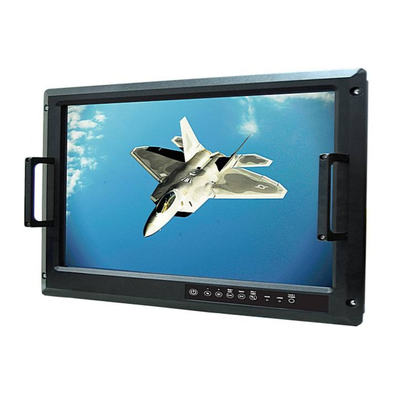
1.1 Introduction Thank you for choosing the Winmate® Military Grade Rack Mount Display. Winmate® Military Grade Displays feature anti-corrosive coating with aluminum alloy housing withstands the harshest military environments. Armored power connector MIL-DTL-38999 Type I initially developed for aerospace industry perfectly fit in our Military grade product line. -
Page 9: Package Contents
Chapter 1: Introduction 1.3 Package Contents Carefully remove the box and unpack your device. Please check if all the items listed below are inside your package. If any of these items are missing or damaged contact us immediately. Standard factory shipment list: ... - Page 10 17~32” Rack Mount Military Display User Manual Dimension 17” Unit: mm CUT OUT 450x368 mm № № Description Description ① ④ AC in 220V ±10%, 50 ± 3% Hz DVI-D ② ⑤ 5 x BNCs RS232 ③ 15 pin D-Sub (VGA)
- Page 11 Chapter 1: Introduction Dimensions 19” Unit : mm CUT OUT 448 x 379 mm № № Description Description ① ④ AC in 220V ±10%, 50 ± 3% Hz DVI-D ② ⑤ 5 x BNCs RS232 ③ 15 pin D-Sub (VGA)
- Page 12 17~32” Rack Mount Military Display User Manual Dimensions 20.1” CUT OUT 446 x 377 mm № № Description Description ① ④ AC in 220V ±10%, 50 ± 3% Hz DVI-D ② ⑤ 5 x BNCs RS-232 ③ 15 pin D-Sub (VGA)
- Page 13 Chapter 1: Introduction Dimensions 24” Unit : mm CUT OUT 562*387 mm № № Description Description ① ④ AC in 220V ±10%, 50 ± 3% Hz DVI-D ② ⑤ 5 x BNCs RS232 ③ 15 pin D-Sub (VGA)
- Page 14 17~32” Rack Mount Military Display User Manual Dimensions 32” Unit : mm CUT OUT mm № № Description Description ① ④ AC in 220V ±10%, 50 ± 3% Hz HDMI in ② ⑤ 15 pin D-Sub (VGA) OSD Control ③ DVI-D...
-
Page 15: Physical Buttons And Led Indicators
Chapter 1: Introduction 1.4 Physical Buttons and LED Indicators On-Screen Display (OSD) is a user-friendly interface to remote the display function and to adjust the display’s image properties. It also supports special Hot Keys for easy control, such as auto- adjustment and brightness control for backlight. -
Page 16: Chapter 2: Getting Started
17~32” Rack Mount Military Display User Manual Chapter 2: Getting Started This chapter provides information on how to connect the device to the source of power, connector pinouts and the guideline to turn on/off the Display. 2.1 Powering On 2.1.1 Power Considerations Follow the recommendations below when powering on the equipment. -
Page 17: Connecting The Power
Chapter 2: Getting Started 2.1.2 Connecting the Power 2.1.2.1 Connecting to AC Input Power Source (Default) AC Power Input Requirements: AC 100~240V, Universal, ±10% Connect one end of the Military Grade power connector MIL-DTL-38999/1 to the Display (CN2), and plug the other end of the power connector (CN1) in to a working AC outlet. Note: Power cords vary in appearance by region and country. - Page 18 17~32” Rack Mount Military Display User Manual 2.1.2.1 Connecting to DC Input Power Source (Optional) DC Power Input Requirements: 9~36V DC IN 1. Insert the exposed wires of the DC Power Cable to the appropriate connectors on the terminal block plug. 2.
-
Page 19: Connecting Other Devices
Chapter 2: Getting Started 2.2 Connecting Other Devices Warning!/ Avertissement! Make sure the power is off when connecting and disconnecting the connectors. Assurez-vous que l'alimentation est coupée lors de la connexion et la déconnexion des connecteurs. 2.2.1 VGA Connector Plug one end of the 15-pin signal cable to the video signal connector at the rear of the PC system and the other end to the Display. -
Page 20: Dvi-I Connector
17~32” Rack Mount Military Display User Manual 2.2.3 DVI-I Connector Plug one end of the DVI signal cable to the video signal connector (DVI-I Dual Link) at the rear of the PC system and the other end to the Display. Pin №... -
Page 21: Chapter 3: Mounting
Chapter 3: Mounting Chapter 3: Mounting This chapter provides mounting guide for all available mounting options. Pay attention to cautions and warning to avoid any damages. Caution/ Attention Follow mounting instructions and use recommended mounting hardware to avoid the risk of injury. Suivez les instructions de montage et d'utilisation recommandé... -
Page 22: Mounting Guide
17~32” Rack Mount Military Display User Manual 3.2 Mounting Guide Military Grade Display comes with different mounting options suitable for most of the industrial and commercial applications. Refer to sub-sections below for more details. 3.2.1 Console / Rack Mount The main mounting approach is rack mount - very user-friendly in terms of installation. Cutout dimensions ( W x D in mm) 24”... -
Page 23: Vesa Mount
Chapter 3: Mounting 3.2.2 VESA Mount Military Rack Mount Display support VESA Mount installation. Notice that VESA Plate is not included in Winmate’s standard accessories package. VESA Plate 24” 32” 17” 19” 100 x 100 mm 100 x 100 mm... -
Page 24: Chapter 4: On-Screen Display Control
17~32” Rack Mount Military Display User Manual Chapter 4: On-Screen Display Control This chapter provides information about On-Screen Display (OSD) Control interfaces. 4.1 Navigating the OSD Menu This section describes how to navigate the OSD Menu. OPTION ACTION EFFECT Display the main menu on the Press the MENU button Enter the main menu screen. -
Page 25: Osd Menu In Vga Mode
Chapter 4: On-Screen Display Control 4.2 OSD Menu in VGA Mode This section describes how to navigate the OSD Menu in VGA Mode. Navigation buttons in VGA Mode BRIGHTNESS CONTRAST VOLUME ADJUST BRICONTRAST AUTO BRIGHTNESS AUDIO SPEAK ON/OFF LED LIGHT MIN BRIGHTNESS ANALOG 1 H-POSITION... - Page 26 17~32” Rack Mount Military Display User Manual You can adjust the value of screen quality automatically. AUTO: Use to choose the best settings for the current input signal CLOCK: Use to adjust the value of horizontal image PHASE: Use to adjust the phase control (Phase adjustment may be required to optimize the display quality) ...
-
Page 27: Osd Menu In Dvi Mode
Chapter 4: On-Screen Display Control OSD EXIT You can exit the OSD menu by selecting “YES”. Select “NO” to return the main menu. 4.3 OSD Menu in DVI Mode This section describes how to navigate the OSD Menu in DVI Mode. Navigation buttons in DVI Mode VOLUME BRICONTRAS... - Page 28 17~32” Rack Mount Military Display User Manual POSITION These functions are not available under DVI mode. IMAGE These functions are not available under DVI mode. COLOR You can fine tune the color temperature by USER option if necessary. USER: Choose RED/GREEN/BLUE to set value of color temperature brightness to suit you own preference...
- Page 29 Chapter 4: On-Screen Display Control AUDIO (optional) You can adjust the setting of speaker, including volume and mute. VOLUME ADJUST: Use to adjust the volume of speaker SPEAK ON/OFF: Use to make the speaker work or mute RECALL You can recall the factory default setting by selecting “YES”.
-
Page 30: Chapter 5: Maintenance
17~32” Rack Mount Military Display User Manual Chapter 5: Maintenance This chapter includes regular cleaning and maintenance procedures. Follow all the recommendations in this chapter in order to ensure long product lifecycle. This equipment is extremely rugged and does not require a lot of maintenance. Remember that electrical equipment should be handled with care and used accordingly to its specifications. -
Page 31: Chapter 6: Technical Support
Chapter 6: Technical Support Chapter 6: Technical Support This chapter includes troubleshooting guide and problem report form. Free technical support is available from our engineers every business day. We are always ready to give advice on application requirements or specific information on the installation and operation of any of our products. -
Page 32: Problem Report Form
17~32” Rack Mount Military Display User Manual 6.2 Problem Report Form Military Grade Rack Mount Display Customer name: Company: Tel.: Fax: E-mail: Date: Product Serial Number: __________________________________________________________ Problem Description: Please describe the problem as clearly as possible. Detailed description of the occurred problem will allow us to find the best solution to solve the problem as soon as possible. -
Page 33: Appendix
Appendix Appendix Appendix A: Product Specifications R17L100- R19L100- R20L100- W24L100- W32L100- Model Name RKA1ML RKA3ML RKA2ML RKS1ML RKA3ML Display 24” 32” Viewable Size 17” 19” 20.1” Image (Widescreen) (Widescreen) Active Display 337.92 (H) x 376.32(H) x 408.0(H) x 518.4 (H)x 698.4(H)x Area, 270.34 (V) mm... -
Page 34: Appendix B: Order Information
17~32” Rack Mount Military Display User Manual Appendix B: Order Information Rack Mount Military Display is available for order in the following configurations: Order Information Item Description 5-wire Resistive Touch Touch 5-wire Resistive Touch with EMI Mesh Coating EMI ITO Glass Power Source Optional: DC 24V, ±10% Appendix C: MIL-STD-810F/G Compliance... -
Page 35: Appendix D: Mil-Std-461E/F Compliance
Appendix Appendix D: MIL-STD-461E/F Compliance This section includes information on testing methods and procedures in compliance with military standard MIL-STD-461 E/F. To comply with MIL-STD-461E Standard, the Display must have Built-in EMI -ITO Glass or Touch with EMI Mesh Film. MIL-STD-461E/F Compliance MIL-STD-461E/F Compliance Test... - Page 36 Winmate Inc. 9F, No.111-6, Shing-De Rd., San-Chung District, New Taipei City 24158, Taiwan, R.O.C Tel: 886-2-8511-0288 Fax: 886-2-8511-0211 Email: sales@winmate.com.tw www.winmate.com...
Need help?
Do you have a question about the R17L100-RKA1ML and is the answer not in the manual?
Questions and answers