
Subscribe to Our Youtube Channel
Related Manuals for Winmate M270TF-XXX


Summary of Contents for Winmate M270TF-XXX
-
Page 1: User Manual
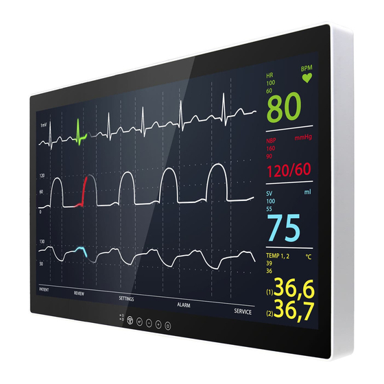
User Manual M270TF-XXX M320TF-XXX LCD Monitor Before operating the unit, please read this manual thoroughly and retain it for future reference. -
Page 2: Table Of Contents
Table of Contents Preface ......................... - 4 - Owner’s Record ......................- 4 - What is Included ......................- 4 - Chapter 1: Hardware Installation ................... - 5 - Installation ......................... - 5 - Connecting Cables ....................- 6 - Ground Pin ........................ - Page 3 Warning and Cautions ..................... - 29 - Safety ........................- 31 - Installation ......................- 31 - Precautions for connecting this unit with other medical devices ......- 31 - Use with an electrosurgical knife, etc..............- 32 - Precautions for using this unit safely ..............
-
Page 4: Preface
Preface Owner’s Record The model and serial numbers are located at the rear of the unit. Record these numbers in the spaces provided below. Refer to these numbers whenever you call upon your Winmate dealer regarding this product. Model No. -
Page 5: Chapter 1: Hardware Installation
Chapter 1: Hardware Installation Installation To access the connectors, remove the connector cover. Before removing the connector cover, disconnect the power cord. 1. Remove the four screws on the connector cover. 2. Slide the connector cover in the direction of the arrow and remove it. Do not remove any other screws other than the four screws affixing the connector cover. -
Page 6: Connecting Cables
Connecting Cables 1. 24 V DC In VGA In 11. Mic In 2. Dual DVI in HDMI 2.0 12. Line Out 3. HDMI 1.4 SDI In 13. RS-232 4. DP1.2 Out SDI Out 14. USB 2.0 5. DP1.2 In 10. RJ-11 15. -
Page 7: Connecting Power
Connecting Power Connect the AC cord to the AC IN terminal on the AC adaptor. Connect the DC OUT terminal of the AC adaptor to the DC IN terminal on the monitor. Align the notch on the cord connector with the guiding groove and plug it in. ... -
Page 8: Soft Power On And Off
Soft Power On and Off The soft power button, when touched, will enable or disable the video screen. The soft power button need only be touched once. Depending on monitor’s current state, there may be a few second delay in displaying an image. Power Modes This table shows the LED light combinations and their meaning: Blue... -
Page 9: Chapter 2: Operating The Device
Chapter 2: Operating the Device IR Remote Control All the monitor controls can be accessed through the IR remote control. This controller has a few quick access keys for the user’s convenience. Soft Power Quick Key – initiates Quick Menu Central Key –... -
Page 10: On Screen Display (Osd) Navigation
On Screen Display (OSD) Navigation When the Enter key is touched, the OSD (On Screen Display) menu will appear on the monitor screen. This menu offers the user ability to make many changes to the image. The table below shows the response after touching the different OSD icons Icon OSD Menu Status Response... -
Page 11: Osd Locking / Unlocking
OSD Locking / Unlocking Touching both the buttons simultaneously will either turn ON or OFF the OSD lockout feature. UNLOCKED LOCKED Hot Keys Touching either the or the button will initiate the brightness control feature. Quick Key The OSD Function key QUICK offers the user easier access to six major monitor adjustment. - Page 12 The sub-menu under ZOOM allows the user the ability to select which image to zoom into. Depending on the Display Mode previously selected, different regions to apply the zoom function are displayed. The sub-menu under SCHEME offers the user six (6) color schemes to choose from. Each color scheme can be adjusted individually under the OSD function DISPLAY, menu option SCHEME ADJUST.
- Page 13 Under Profile, the sub-menu offers the user six (6) different previously saved 3D LUT (Look Up Table) profiles to select from. Profile can be uploaded using the Tomlinson Color calibration software (not included). Source 1 Set Main Video Input Zoom Zoom in / Zoom out of an image Select the uploaded scheme file Scheme...
-
Page 14: Basic Osd Menu Options: Display
Basic OSD Menu Options: Display The OSD offers a variety of monitor adjustment capabilities. Below is a description of a few common functions used. Under SCHEME ADJUST, the HUE and Saturation of each primary and secondary color can be changed. These changes are stored under the SCHEME currently activated. (Found under the Quick Menu) Under COLOR CONTROL, the RED, GREEN, and BLUE colors of the current image are changed. - Page 15 Adjusts the overall image and background brightness Brightness Value: 0-100 Adjusts the image contrast in relationship to the background Contrast Value: 0-100 Adjusts the crispness of the image Sharpness Value: 0 to 4 Adjusts the Auto Display Control (ADC) brightness Brightness Value: 0-100 Adjusts the color temperature of the entire screen.
-
Page 16: Basic Osd Menu Options: Adjust
Basic OSD Menu Options: Adjust The ADJUST feature will automatically adjust an analog image. When an analog image is initially detected, the monitor will attempt to automatically adjust the image positioning. This automatic adjustment feature can be turned On/Off here. Adjust the white balance automatically here by selecting PRESS ENTER - 16 -... - Page 17 Automatically adjusts screen size, H position, V position, Clock, AUTO Adjust Clock Phase when video source is changed Controls the horizontal position of the image within the display H Position area of the LCD. Value: 0-100 Controls the vertical position of the image within the display area V Position of the LCD.
-
Page 18: Basic Osd Menu Options: Audio
Basic OSD Menu Options: Audio The speaker volume for all audio inputs is controlled here. AUDIO SOURCE allows the user to select which from the available inputs. Example, there are 3 regions within the Quad display with audio. Adjusts the level of volume Volume - Decrease + Increase... -
Page 19: Basic Osd Menu Options: Multi-Display
Basic OSD Menu Options: Multi-Display Display mode offer the user up to five different layouts to view input images Each source can be assigned an active image (only one source can be set to auto scan) - 19 -... - Page 20 Under the PIP layout position and size of the inner image can be adjusted Choose the Display Mode Display Mode Full, 2PLR, 2PTB, PIP or QUAD Choose the channel of display source Source 1 Auto Scan/VGA/DVI/HDMI 2.0/HDMI 1.4/DP Choose the channel of display source Source 2 Auto Scan/VGA/DVI/HDMI 2.0/HDMI 1.4/DP Choose the channel of display source...
-
Page 21: Basic Osd Menu Options: Osd
Basic OSD Menu Options: OSD Selecting MONITOR INFO will display the current state of the monitor. PCB version, firmware version, serial number, and inputs. Set the time of auto close OSD menu OSD Turn Off Value: 0-60 sec Adjust the horizontal and vertical location where the OSD OSD Position appears on the screen Value: 0-100... -
Page 22: Basic Osd Menu Options: Advanced
Basic OSD Menu Options: ADVANCED By selecting SCALING, the user can choose the perspective the image is displayed in. The ability to control the monitor’s functions by way of an infrared remote can be enabled/disabled here. - 22 -... - Page 23 Adjust the image scaling setting Scaling Full/16:10/16:9/4:3/5:4/1:1 Set the flip image mode Flip Rotate 0 / Rotate 90 / Rotate 180 / Rotate 270 / LEFT/RIGHT /UP/DOWN Perform over scan function Overscan Under scan Over Scan RGB/YUV RGB/YUV Can Switch Between Color Spaces Select the RS232 signal source: local COM or Fiber RS232 Local / Fiber...
-
Page 24: Chapter 3: Important Information
This product has been manufactured by Winmate Inc. Inquiries related to product compliance based on European Union legislation shall be addressed to the authorized representative, Winmate. For any service or guarantee matters, please refer to the addresses provided in the separate service or guarantee documents. -
Page 25: Important Safeguards/Notices For Use In The Medical Environments
Important EMC notices for use in the medical environments The M270TF-XXX / M320TF-XXX needs special precautions regarding EMC and needs to be installed and put into service per the EMC information provided in the instructions for use. - Page 26 Guidance and manufacturer’s declaration-electromagnetic emissions The M270TF-XXX / M320TF-XXX is intended for use in the electromagnetic environment specified below. The customer or the user of the M270TF-XXX / M320TF-XXX should assure that it is used in such an environment. Emission test...
- Page 27 Guidance and manufacturer’s declaration - electromagnetic immunity The M270TF-XXX / M320TF-XXX is intended for use in the electromagnetic environment specified below. The customer or the user of the M270TF-XXX / M320TF-XXX should assure that it is used in such as environment. Immunity test...
- Page 28 The M270TF-XXX / M320TF-XXX is intended for use in an electromagnetic environment in which radiated RF disturbances are controlled. The customer or the user of the M270TF-XXX / M320TF-XXX can help prevent electromagnetic interference by maintaining a minimum distance between portable and mobile RF communications equipment (transmitters) and the M270TF-XXX / M320TF-XXX as recommended below, per the maximum output power of the communications equipment.
-
Page 29: Warning And Cautions
To prevent injuries, firmly fix the unit to the floor or wall following the installation manual. WARNING ! If the M270TF-XXX / M320TF-XXX should be used adjacent to or stacked with other equipment, it should be observed to verify normal operation in the configuration in which it will be used. - Page 30 Warning on power connection: Use a proper power cord for your local power supply. Use the approved Power Cord (3-core mains lead) / Appliance Connector /Plug with earthing-contacts that conforms to the safety regulations of each country if applicable. Use the Power Cord (3-core mains lead) / Appliance Connector / Plug WARNING ! conforming to the proper ratings (Voltage, Ampere).
-
Page 31: Safety
Safety M270TF-XXX / M320TF-XXX is a DC powered device. Use with the supplied AC adaptor (EM11701F). Operate the unit on 100-240V AC only. The nameplate indicating operating voltage, etc. is located on the AC adaptor. Should any solid object or liquid fall into the cabinet, unplug the unit and have it checked by qualified personnel before operating it any further. -
Page 32: Use With An Electrosurgical Knife, Etc
Use with an electrosurgical knife, etc. If this unit is used together with an electrosurgical knife, etc., the picture may be disturbed, warped or otherwise abnormal because of strong radio waves or voltages from the device. This is not a malfunction. When you use this unit simultaneously with a device from which strong radio waves or voltages are emitted, confirm the effect of this before using such devices, and install this unit in a way that minimizes the effect of radio wave interference. -
Page 33: About The Lcd Display Panel
About the LCD Display Panel The LCD panel fitted to this unit is manufactured with high precision technology, giving a functioning pixel ratio of at least 99.99%. Thus, a very small proportion of pixels may be “stuck”, either always off (black), always on (red, green, or blue), or flashing. -
Page 34: A Long Period Of Use
A long period of use Due to the characteristics of LCD panel, displaying static images for extended periods, or using the unit repeatedly in a high temperature/high humidity environments may cause image smearing, burn-in, areas of which brightness is permanently changed, lines, or a decrease in overall brightness. -
Page 35: Flat Surface For Better Maintenance
Do not use unnecessary force to rub the protection plate surface/monitor surface with a stained cloth. The protection plate surface/monitor surface may be scratched. Do not keep the protection plate surface/monitor surface in contact with a rubber or vinyl resin product for a long period of time. -
Page 36: Biological Hazard And Returns
Biological Hazard and Returns The structure and the specifications of this device as well as the materials used for manufacturing makes it easy to wipe and clean and therefore suitable to be used for various applications in hospitals and other medical environments, where procedures for frequent cleaning are specified. -
Page 37: Frequency Table
Frequency Table Vertical HDMI HDMI Signal name Frequency DP 1.2 (Hz) ✔ ✔ ✔ ✔ ✔ ✔ ✔ ✔ ✔ ✔ 640 x 480 ✔ ✔ ✔ ✔ ✔ ✔ ✔ ✔ ✔ ✔ ✔ ✔ ✔ ✔ ✔ ✔ 480P ✔... -
Page 38: Troubleshooting
Troubleshooting Problem Check the following There is a black dot or A missing pixel does not constitute an out of spec. dead pixel dot on the defective product screen Turn off the power supply, and check that the AC cord Cannot turn power on or DC cord are securely inserted. -
Page 39: Appendix A: Technical Specification
Appendix A: Technical Specification Monitor M270TF-XX M320TF-XX LED Backlight Technology, LED Backlight Technology, TFT TFT Active-matrix, Active-matrix, Widescreen, IPS Widescreen, IPS Technology Technology Screen Technology Optional for Visual and Safety Optional for Visual and Safety Enhancement Layer (VSEL) Enhancement Layer (VSEL) Bonding Bonding... - Page 40 643.17 x 408.06 x 48 mm 777.58 x 477.62 x 48 mm Product Dimensions (25.3 x 16.1 x 1.8 in) (30.6 x 18.8 x 1.8 in) VESA mounting 100 x 100mm VESA mounting 100 x 100mm Mounting VESA mounting 200 x 100mm VESA mounting 200 x 100mm VESA mounting 300 x 100mm Product Weight...
- Page 41 SDI Resolution, frame rate and cable Resolution Frame Rate & Structure SDI Cable 1920x1080 60/P 1920x1080 50/P 1920x1080 60/I RG59 or RG6 1920x1080 50/I RG59 or RG6 1920x1080 30/P RG59 or RG6 1920x1080 25/P RG59 or RG6 1920x1080 24/P RG59 or RG6 1920x1080 30/PsF RG59 or RG6...
- Page 42 AC Adapter Pin assignment and signal name of AC adapter DC OUT terminal Pin No. Signal Name DC 24 V DC 24 V AC 100 V – 240 V 50 Hz/60 Hz – 1.2 A AC IN 179 mm (7.04″) × 40 mm (1.5″) × 65 mm (2.5″) Dimensions (W ×...
- Page 43 PIN Specification Pin assignment and signal name of RS-232 C terminal Signal Name Signal Name NC (no connection) Transmission data Reception data Short circuit at pin 6 on the monitor Short circuit at pin 4 on the monitor Short circuit at pin 8 on the monitor Short circuit at pin 7 on the monitor NC (no connection) Pin assignment and signal name of HD15 input terminal (mini D-Sub 15 pin)
- Page 44 Pin assignment and signal name of DVI-D terminal Pin No. Signal Name Pin No. Signal Name DVI_RX2- DVI_CON_HP DVI_RX2- DVI_RX0- DVI_RX0+ DVI_RX4- DVI_RX4+ DVI_RX5- DVI SCL DVI_RX5+ DVI SDA DVI_CLKP DVI_RX1- DVI_CLKN DVI_RX1+ DVI_RX3- DVI_RX3+ +5V_DVI DVI_CON_CABLE _DETECT Pin assignment and signal name of DP-IN Pin No.
- Page 45 Return DP_PWR Pin assignment and signal name of SDI-IN Pin No. Pin No. Signal Name Signal Name Pin assignment and signal name of SDI-Out Pin No. Pin No. Signal Name Signal Name Pin assignment and signal name of HDMI Pin No. Pin No.
- Page 46 Data- Data+ Pin assignment and signal name of Power Pin No. Pin No. Signal Name Signal Name - 46 -...
-
Page 47: Dimensional Figure
Dimensional Figure 27” Model 32” Model - 47 -... -
Page 48: Appendix B: Meaning Of Symbols On The Unit
Appendix B: Meaning of Symbols on the unit Symbol Description Symbol Description Symbol Description Potential This device equalization complies with the terminal (Sets Medical Device Serial number other devices to Directive same potential 93/42/EEC level) Date of Manufacturer/prod Direct current manufacture uct owner Stacking limit by... - Page 49 Information on Disposal in other Countries outside the European Union. Winmate reserves the right to make changes in specifications and features shown herein, or discontinue the product at any time without notice or obligation.” Information on Disposal for Users of Waste Electrical & Electronic Equipment (private...
- Page 50 NOTES _________________________________________________________ _________________________________________________________ _________________________________________________________ _________________________________________________________ _________________________________________________________ _________________________________________________________ _________________________________________________________ _________________________________________________________ _________________________________________________________ _________________________________________________________ _________________________________________________________ _________________________________________________________ _________________________________________________________ _________________________________________________________ _________________________________________________________ _________________________________________________________ _________________________________________________________ _________________________________________________________...
- Page 52 Winmate Inc. 9F, No.111-6, Shing-De Rd., San-Chung District, New Taipei City 24158, Taiwan, R.O.C Tel: 886-2-8511-0288 Fax: 886-2-8511-0211 Email: sales@winmate.com.tw Official website: www.winmate.com...
Need help?
Do you have a question about the M270TF-XXX and is the answer not in the manual?
Questions and answers