Table of Contents

Related Manuals for Winmate R08L100-MLU1


Summary of Contents for Winmate R08L100-MLU1
-
Page 1: User Manual
8.4/ 10.4 G-WIN Military Display Model No.: R08L100-MLU1 R10L100-MLT2 R10L100-MLP1 User Manual Version 1.0 Document Part Number: 9152150I1008 Please read this instructions before operating the device and retain them for future reference. -
Page 2: Table Of Contents
8.4/ 10.4 G-WIN Military Display User Manual Contents Preface ........................... 3 About This User Manual ..................... 7 Chapter 1: Introduction ....................8 1.1 About G-WIN Military Display ................9 1.2 Product Features ....................9 1.3 Package Overview ....................9 1.4 Mechanical Concept ................... 10 1.5 Product Overview .................... -
Page 3: Preface
Preface Preface Copyright Notice No part of this document may be reproduced, copied, translated, or transmitted in any form or by any means, electronic or mechanical, for any purpose, without the prior written permission of the original manufacturer. Trademark Acknowledgement Brand and product names are trademarks or registered trademarks of their respective owners. - Page 4 8.4/ 10.4 G-WIN Military Display User Manual Advisory Conventions Four types of advisories are used throughout the user manual to provide helpful information or to alert you to the potential for hardware damage or personal injury. These are Notes, Important, Cautions, and Warnings.
-
Page 5: Safety Information
Preface Safety Information Warning!/ Avertissement! Always completely disconnect the power cord from your chassis whenever you work with the hardware. Do not make connections while the power is on. Sensitive electronic components can be damaged by sudden power surges. Only experienced electronics personnel should open the PC chassis. Toujours débrancher le cordon d’alimentation du chassis lorsque vous travaillez sur celui-ci. -
Page 6: Safety Precautions
8.4/ 10.4 G-WIN Military Display User Manual Safety Precautions For your safety carefully read all the safety instructions before using the device. Keep this user manual for future reference. Always disconnect this equipment from any AC outlet before cleaning. Do not use liquid or spray detergents for cleaning. -
Page 7: About This User Manual
Preface About This User Manual This User Manual provides information about using the Winmate® G-WN Military Display. The documentation set provides information for specific user needs, and includes: G-WIN Military Display User Manual – contains detailed description on how to use the display, its components and features. -
Page 8: Chapter 1: Introduction
8.4/ 10.4 G-WIN Military Display User Manual Chapter 1: Introduction This chapter gives you product overview, describes features and hardware specification. You will find all accessories that come with the display device in the packing list. Mechanical dimensions and drawings included in this chapter. -
Page 9: About G-Win Military Display
MIL-STD 810F that withstands shocks and vibration. 1.2 Product Features Winmate® G-WIN Military Display features: 8.4/ 10.4” LCD Full IP65 dust and water protection (Except I/ O parts) ... -
Page 10: Mechanical Concept
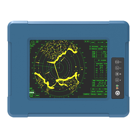
8.4/ 10.4 G-WIN Military Display User Manual 1.4 Mechanical Concept On the picture below you can see spare parts exploded drawing of a standard G-WIN Military Display. 1.5 Product Overview This section describes physical appearance of the G-WIN Military Display. All dimensions shown in mm. R08L100-MLU1... - Page 11 Chapter 1: Introduction R10L100-MLT2 R10L100-MLP1...
-
Page 12: External Connectors
8.4/ 10.4 G-WIN Military Display User Manual 1.6 External Connectors Terminal interfaces are located on the rear bottom side of the display. Item Description RS232 for Touch - Connects touch interface to the monitor. Example: A touch to a monitor. Power Input - Military grade lockable power connector (MS27467T9F98S). -
Page 13: Chapter 2: Installation
Chapter 2: Installation Chapter 2: Installation This chapter provides hardware installation instructions and mounting guide for all available mounting options. Pay attention to cautions and warning to avoid any damages... -
Page 14: Cable Mounting Considerations
8.4/ 10.4 G-WIN Military Display User Manual 2.1 Cable Mounting Considerations For a nice look and safe installation, make sure cables are neatly hidden behind the display. Warning!/ Avertissement! Observe all local installation requirements for connection cable type and protection level. Suivre tous les règlements locaux d’installations, de câblage et niveaux de protection. - Page 15 Chapter 2: Installation Connecting to Power Source Connect a power cable to military power connector located on the back side of the display. Connect open wires to the source of power.
-
Page 16: Mounting Guide
8.4/ 10.4 G-WIN Military Display User Manual 2.3 Mounting Guide The device comes with different mounting options suitable for most of the industrial and commercial applications. There are two main mounting approaches - Dash/ Yoke Mount and VESA mount; both approaches are very easy for user to set up the display. 2.3.1 VESA Mount G-WIN Military Display compatible with VESA mount solution. -
Page 17: Yoke Mount
Chapter 2: Installation 2.3.2 Yoke Mount Yoke Mount solution allows to mount your device on a wall or ceiling. You can purchase dash/ yoke mounting kit from Winmate as an optional accessory. Yoke Mounting Kit: Size Winmate Part Number 8.4”... -
Page 18: Roof Mount
4. Loosen the hand-screw adjustment tool, then you can adjust product angle on the stand. Then screw the product tightly again to secure the stand position. 2.3.3 Roof Mount Roof mounting allows mounting your device on the roof. You can purchase roof mounting kit from Winmate as an optional accessory. U-Shape Mounting Kit:... - Page 19 Chapter 2: Installation U-Shape Mounting Kit Mechanical Drawing For 8.4” G-WIN Military Display: For 10.4” G-WIN Military Display:...
-
Page 20: Connecting Peripherals
8.4/ 10.4 G-WIN Military Display User Manual 2.4 Connecting Peripherals This Display comes with VGA interface located on the bottom panel. For a nice look and safe installation, make sure cables are neatly hidden behind the device. Caution/ Attention Observe all local installation requirements for connection cable type and protection level. -
Page 21: Connector Description
Chapter 2: Installation 2.5 Connector Description The panel control port is designed for monitors that work with a variety of compatible video sources. Due to the possible deviations between these signal sources, you may have to make adjustments to the monitor settings from the OSD menu when switching between these sources. Note: Notice that standard input terminals include VGA. -
Page 22: Chapter 3: Operating The Device
8.4/ 10.4 G-WIN Military Display User Manual Chapter 3: Operating the Device In this chapter you will find instructions on how to operate the display. -
Page 23: Turning On/ Off The System
Chapter 3: Operating the Device 3.1 Turning On/ Off the System To turn on the system: 1. Connect VGA cable to the connector of your device. 2. Connect the other side of VGA cable to external computer. 3. Turn on the external computer. 4. -
Page 24: On-Screen Display Menu Navigation
8.4/ 10.4 G-WIN Military Display User Manual 3.3 On-Screen Display Menu Navigation OSD Icon Sub-menu Settings Note BRIGHTNESS slider bar Default 50 Use to adjust the screen’s brightness. Range 0 to 100. CONTRAST slider bar Default 50 BRICONTRAST Use to adjust the screen’s contrast. Range 0 to 100. H POSITION slider bar VGA only. -
Page 25: Appendix
Appendix Appendix This chapter contains additional product information, including troubleshooting guide and frequency table... -
Page 26: Appendix A: Hardware Specifications
8.4/ 10.4 G-WIN Military Display User Manual Appendix A: Hardware Specifications R08L100-MLU1 R10L100-MLT2 R10L100-MLP1 Display 8.4” 10.4” 10.4” Size/ Type Resolution 800 x 600 1024 x 768 800 x 600 Brightness 600 nits 350 nits 400 nits Contrast Ratio 600:1 (typ.) 1200:1(typ.) -
Page 27: Appendix B: Frequency Table
Appendix Appendix B: Frequency Table The choice of supported modes depends on the monitor native resolution. Refer to the table below for more information about available input signals. Signal name Frequency (Hz) 800x600 50/ 60/ 72/ 75 1024x768 60/ 70/ 75 Appendix D: Cleaning the Monitor Before cleaning: ... - Page 28 Winmate Inc. 9F, No.111-6, Shing-De Rd., San-Chung District, New Taipei City 24158, Taiwan, R.O.C www.winmate.com Copyright © Winmate Inc. All rights reserved.
Need help?
Do you have a question about the R08L100-MLU1 and is the answer not in the manual?
Questions and answers