
Related Manuals for Winmate R10L100-PPT2HB


Summary of Contents for Winmate R10L100-PPT2HB
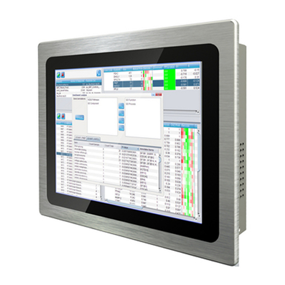
- Page 1 High Brightness P-Cap Panel Mount Display 10.4~21.5” User Manual Version 1.1 Document Part Number: 91521110103F Please read this instructions before operating the device and retain them for future reference.
-
Page 2: Table Of Contents
10.4~21.5" High Brightness P-Cap Panel Mount Display User Manual Contents Preface About This User Manual Chapter 1: Introduction 1.1 Overview ......................9 1.2 Product Features ....................9 1.3 Package Contents ....................9 1.4 Physical Appearance ..................10 1.5 Connector Description ..................13 1.6 OSD Control Panel ..................... -
Page 3: Preface
Preface Preface Copyright Notice No part of this document may be reproduced, copied, translated, or transmitted in any form or by any means, electronic or mechanical, for any purpose, without the prior written permission of the original manufacturer. Trademark Acknowledgement Brand and product names are trademarks or registered trademarks of their respective owners. - Page 4 10.4~21.5" High Brightness P-Cap Panel Mount Display User Manual Naming Rule R10L100-PPT2HB Item Description Panel Type Panel Size LXXX Product Size Mechanical Type (P-Cap Panel Mount) Panel Model Feature (High Brightness) Advisory Conventions Four types of advisories are used throughout the user manual to provide helpful information or to alert you to the potential for hardware damage or personal injury.
- Page 5 Preface Safety Information Warning!/ Avertissement! Always completely disconnect the power cord from your chassis whenever you work with the hardware. Do not make connections while the power is on. Sensitive electronic components can be damaged by sudden power surges. Only experienced electronics personnel should open the PC chassis.
- Page 6 10.4~21.5" High Brightness P-Cap Panel Mount Display User Manual Safety Precautions For your safety carefully read all the safety instructions before using the device. Keep this user manual for future reference. Always disconnect this equipment from any AC outlet before cleaning. Do not use liquid or spray detergents for cleaning.
-
Page 7: About This User Manual
About This User Manual About This User Manual This User Manual provides information about using the Winmate® High Brightness P-Cap Panel Mount Display. The documentation set provides information for specific user needs, and includes: Panel Mount Display User Manual – contains detailed description on how to use the display, its components and features. -
Page 8: Chapter 1: Introduction
10.4~21.5" High Brightness P-Cap Panel Mount Display User Manual Chapter 1: Introduction This chapter gives you product overview, describes features and hardware specification. You will find all accessories that come with the display device in the packing list. Mechanical dimensions and drawings included in this chapter. -
Page 9: Overview
Chapter 1: Introduction 1.1 Overview Congratulations on purchasing Winmate® High Brightness P-Cap Display. Versatile display in an open-frame housing designed for wall mount and VESA mount solutions for industrial applications. 1.2 Product Features Winmate® High Brightness P-Cap Display features: 10.4-21.5” TFT LCD ... -
Page 10: Physical Appearance
1.4 Physical Appearance This section describes appearance, connectors’ layout and mechanical dimensions of the display. Notice that this is a simplified drawing and some components are not marked in detail. 10.4-inch, R10L100-PPT2HB Unit: mm Dimensions :284 x 252 x 55 10.4-inch, R10L100-PPP1HB... - Page 11 Chapter 1: Introduction 15-inch, R15L600-PPC3HB Unit: mm Dimensions :420 x 320 x 57 15-inch, W15L100-PPA2HB Unit: mm Dimensions :444 x 285 x 58.5...
- Page 12 10.4~21.5" High Brightness P-Cap Panel Mount Display User Manual 19-inch, R19L300-PPA1HB Unit: mm Dimensions :474 x 384 x 76.5 21.5-inch, W22L100-PPA3HB Unit: mm Dimensions :550 x 370 x 69.5...
-
Page 13: Connector Description
Chapter 1: Introduction 1.5 Connector Description This section describes physical appearance of the display. Note: Notice that standard input terminals include VGA and HDMI. Your device may be equipped with DVI, S-Video or Composite input terminals based on your order. Notice that input and output connectors vary by product size and specifications. -
Page 14: Osd Control Panel
10.4~21.5" High Brightness P-Cap Panel Mount Display User Manual 1.6 OSD Control Panel 1.6.1 Control Buttons OSD control panel is located on the bottom side of the display. Icon Function Decrease the value / Select up Increase the value / Select down Power switch Exit / Auto adjustment Enter / Call main OSD menu... -
Page 15: Chapter 2: Installation
Chapter 2: Installation Chapter 2: Installation This chapter provides hardware installation instructions and mounting guide for all available mounting options. Pay attention to cautions and warning to avoid any damages... -
Page 16: Wiring Requirements
10.4~21.5" High Brightness P-Cap Panel Mount Display User Manual 2.1 Wiring Requirements The following common safety precautions should be observed before installing any electronic device: Strive to use separate, non-intersecting paths to route power and networking wires. If power wiring and device wiring paths must cross make sure the wires are perpendicular at the intersection point. -
Page 17: Mounting Guide
Chapter 2: Installation 2.2 Mounting Guide The Panel Mount Display supports different installation methods, including panel mount, VESA mount. Refer to sub-sections below for more details. Caution/ Attention Follow mounting instructions and use recommended mounting hardware to avoid the risk of injury. Suivez les instructions de montage et d'utilisation recommandé... -
Page 18: Vesa Mount
Panel Mount Display comes with VESA holes for wall/ desk mounting. Installation Instruction: 1. Screw VESA bracket to the fixture (ex. swing arm) with four VESA screws. 2. Place the device on VESA bracket. Notice that VESA stand and mounting kit are not provided by Winmate. -
Page 19: Cable Mounting Considerations
Chapter 2: Installation 2.3 Cable Mounting Considerations For a nice look and safe installation, make sure cables are neatly hidden behind the device. Caution/ Attention Observe all local installation requirements for connection cable type and protection level. Suivre tous les règlements locaux d’installations, de câblage et niveaux de protection. -
Page 20: Connecting Peripherals
10.4~21.5" High Brightness P-Cap Panel Mount Display User Manual 2.5 Connecting Peripherals The panel control port is designed for monitors that work with a variety of compatible video sources. Due to the possible deviations between these signal sources, you may have to make adjustments to the monitor settings from the OSD menu when switching between these sources. -
Page 21: Dvi Connector
Chapter 2: Installation 2.5.3 DVI Connector Notice that DVI is an optional connector and may not be present in your device. Use DVI to connector in the rear of PC system, and plug the other end to the TFT LCD display. Fasten cable connectors with screws. -
Page 22: Chapter 3: Operating The Device
10.4~21.5" High Brightness P-Cap Panel Mount Display User Manual Chapter 3: Operating the Device In this chapter you will find instructions on how to operate the display. -
Page 23: Turning On The System
Chapter 3: Operating the Device 3.1 Turning on the System To turn on the system: 1. Connect the power adapter cable to the DC input of the display. 2. Connect the power cord to the power adapter. 3. Connect the power cord to a power outlet. 4. -
Page 24: Osd Menu Navigation
10.4~21.5" High Brightness P-Cap Panel Mount Display User Manual 3.2 OSD Menu Navigation OSD Icon Sub-menu Settings Note BRIGHTNESS slider bar Default 50 Use to adjust the screen’s brightness. Range 0 to 100 CONTRAST slider bar Default 50 BRICONTRAST Use to adjust the screen’s contrast. Range 0 to 100 H POSITION slider bar Default 50... - Page 25 Chapter 3: Operating the Device OSD Icon Sub-menu Settings Note AUTO SCAN Select and execute Default mode Auto detect the input source ANALOG Select and execute Switch the setting of signal input to Analog mode CHANNEL HDMI Select and execute Switch the setting of signal input to HDMI mode Select and execute Recall the factory default setting...
-
Page 26: Troubleshooting Guide
10.4~21.5" High Brightness P-Cap Panel Mount Display User Manual 3.3 Troubleshooting Guide If your monitor fails to operate correctly, check the following chart for possible solution before calling for repairs: Condition Check Point • Check if the signal cable is firmly seated in the socket. The picture does not •... -
Page 27: Appendix
Appendix Appendix This chapter contains additional product information, including troubleshooting guide and frequency table... -
Page 28: Appendix A: Frequency Table
10.4~21.5" High Brightness P-Cap Panel Mount Display User Manual Appendix A: Frequency Table The choice of supported modes depends on the monitor native resolution. Refer to the table below for more information about available input signals. A-1 Separate RGB Video Signal (VGA) Input Timing Input Timing Range: H : 30-80KHz;... -
Page 29: Supported Hdmi Mode
Appendix A-4 Supported HDMI Mode Mode Resolution Mode 1 480i Mode 2 576i Mode 3 480p Mode 4 576p Mode 5 720p Mode 6 1080i Mode 7 1080p... -
Page 30: Appendix B: Hardware Specifications
10.4~21.5" High Brightness P-Cap Panel Mount Display User Manual Appendix B: Hardware Specifications Model Name R10L100-PPT2HB R10L100-PPP1HB R15L600-PPC3HB Display 10.4” 10.4” 15” Size/Type Resolution 1024x768 800x600 1024x768 Brightness 1000 nits 1000 nits 1000 nits Contrast Ratio 1000:1 (typ.) 500:1 (typ.) 700:1 (typ.) - Page 31 Appendix Model Name W15L100-PPA2HB R19L300-PPA1HB W22L100-PPA3HB Display 15.6” 19” 21.5” Size/Type Resolution 1366x768 1280x1024 1920x1080 Brightness 1300 nits 1000 nits 1000 nits Contrast Ratio 500:1 (typ.) 1000:1 (typ.) 5000:1 (typ.) Viewing Angle -85~85(H);-80~80(V) -85~85(H) ; -80~80(V) -89~89(H) ; -89~89(V) Active Display Area 344.232(H)x 193.536(V) 376.32(H)x301.056(V) 476.64 (H) x 268.11 (V)
- Page 32 Winmate Inc. 9F, No.111-6, Shing-De Rd., San-Chung District, New Taipei City 24158, Taiwan, R.O.C www.winmate.com Copyright © Winmate Inc. All rights reserved.
Need help?
Do you have a question about the R10L100-PPT2HB and is the answer not in the manual?
Questions and answers