
Subscribe to Our Youtube Channel
Related Manuals for Winmate R19L100-MLM1


Summary of Contents for Winmate R19L100-MLM1
- Page 1 19” G-WIN Military Display R19L100-MLM1 User Manual Version 1.0 Document Part Number: 91521110103A Please read this instructions before operating the device and retain them for future reference.
-
Page 2: Table Of Contents
19" G-WIN Military Display User Guide Contents Preface ........................... 3 About This User Guide ....................7 Chapter 1: Introduction ....................8 1.1 About G-WIN Military Display ................9 1.2 Product Features ....................9 1.3 Package Overview ....................9 1.4 Product Overview ....................10 1.5 External Connectors ................... -
Page 3: Preface
Preface Preface Copyright Notice No part of this document may be reproduced, copied, translated, or transmitted in any form or by any means, electronic or mechanical, for any purpose, without the prior written permission of the original manufacturer. Trademark Acknowledgement Brand and product names are trademarks or registered trademarks of their respective owners. - Page 4 19" G-WIN Military Display User Guide Advisory Conventions Four types of advisories are used throughout the user manual to provide helpful information or to alert you to the potential for hardware damage or personal injury. These are Notes, Important, Cautions, and Warnings. The following is an example of each type of advisory. Note: A note is used to emphasize helpful information Important:...
- Page 5 Preface Safety Information Warning!/ Avertissement! Always completely disconnect the power cord from your chassis whenever you work with the hardware. Do not make connections while the power is on. Sensitive electronic components can be damaged by sudden power surges. Only experienced electronics personnel should open the PC chassis. Toujours débrancher le cordon d’alimentation du chassis lorsque vous travaillez sur celui-ci.
- Page 6 19" G-WIN Military Display User Guide Safety Precautions For your safety carefully read all the safety instructions before using the device. Keep this user manual for future reference. Always disconnect this equipment from any AC outlet before cleaning. Do not use liquid or spray detergents for cleaning.
-
Page 7: About This User Guide
Preface About This User Manual This User Manual provides information about using the Winmate® G-WN Military Display. The documentation set provides information for specific user needs, and includes: G-WIN Military Display User Manual – contains detailed description on how to use the display, its components and features. -
Page 8: Chapter 1: Introduction
19" G-WIN Military Display User Guide Chapter 1: Introduction This chapter gives you product overview, describes features and hardware specification. You will find all accessories that come with the display device in the packing list. Mechanical dimensions and drawings included in this chapter. -
Page 9: About G-Win Military Display
The ultra-rugged display was developed to survive in-vehicle military applications with MIL-STD 810F that withstands shocks and vibration. 1.2 Product Features Winmate® G-WIN Military Display features: 19-inch 1280x1024 panel with ITO EMI shielding protection glass Front sealed IP67 aluminum compact housing design ... -
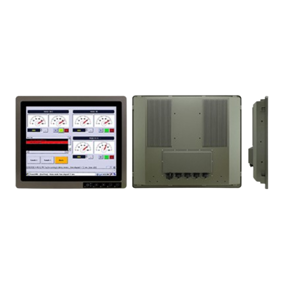
Page 10: Product Overview
19" G-WIN Military Display User Guide 1.4 Product Overview This section describes physical appearance of the G-WIN Military Display. All dimensions shown in mm. R19L100-MLM1 1.5 External Connectors Terminal interfaces are located on the rear bottom side of the display. Item Description Power Input - Military grade lockable power connector (MS27467T9F98S). -
Page 11: Physical Buttons And Led Indicators
Chapter 1: Introduction 1.6 Physical Buttons and LED Indicators Physical buttons and LED indicators located in front or on the rear side of the Display. Physical Buttons Icon Function Esc -. When OSD is enabled, it returns to the previous menu level or closes the OSD if pressed at the Main Menu level. -
Page 12: Chapter 2: Installation
19" G-WIN Military Display User Guide Chapter 2: Installation This chapter provides hardware installation instructions and mounting guide for all available mounting options. Pay attention to cautions and warning to avoid any damages... -
Page 13: Cable Mounting Considerations
Chapter 2: Installation 2.1 Cable Mounting Considerations For a nice look and safe installation, make sure cables are neatly hidden behind the display. Warning!/ Avertissement! Observe all local installation requirements for connection cable type and protection level. Suivre tous les règlements locaux d’installations, de câblage et niveaux de protection. - Page 14 19" G-WIN Military Display User Guide Connecting to Power Source Connect a power cable to military power connector located on the back side of the display. Connect open wires to the source of power. Warning!/ Avertissement! Serious injury due to shock is possible if unit is wired incorrectly or connected to voltage exceeding the input voltage range.
-
Page 15: Mounting Guide
Chapter 2: Installation 2.3 Mounting Guide 19” G-WIN Military Display supports wall mount and compatible with VESA mount solution. Follow the instruction below to complete mounting. 2.3.1 Wall Mount Follow instructions below to mount 19” G-WIN Military Display into the wall. Mounting Steps:... -
Page 16: Vesa Mount
4. When the installation is complete, plug the power cord into a grounded AC outlet. Turn on the power. *Notice that VESA stand and mounting kit are not provided by Winmate. 2.4 Connecting Peripherals This Display comes with VGA and DVI interface located on the bottom panel. For a nice look and safe installation, make sure cables are neatly hidden behind the device. - Page 17 Chapter 2: Installation Caution/ Attention Turn off the device and disconnect other peripherals before installation. Éteindre l’appareil et débrancher tous les périphériques avant l’installation. To display video and sound from an external PC follow the instructions below. 1. Turn off your computer and unplug external computer's power cable. 2.
-
Page 18: Connector Description
19" G-WIN Military Display User Guide Connecting display to external PC via DVI: 2.5 Connector Description The panel control port is designed for monitors that work with a VGA, DVI-D video sources. Due to the possible deviations between these signal sources, you may have to make adjustments to the monitor settings from the OSD menu when switching between these sources. -
Page 19: Dvi-D Connector
Chapter 2: Installation 2.5.2 DVI-D Connector Plug DVI signal cable to the DVI-D (Dual Link) connector in the rear of PC system, and plug the other end to the monitor. Secure cable connectors with screws. Pin Assignment and signal names for DVI-D (Dual Link) connector Pin №... -
Page 20: Chapter 3: Operating The Device
19" G-WIN Military Display User Guide Chapter 3: Operating the Device In this chapter you will find instructions on how to operate the display. -
Page 21: Turning On/ Off The System
Chapter 3: Operating the Device 3.1 Turning On/ Off the System To turn on the system: 1. Connect VGA cable to the connector of your device. 2. Connect the other side of VGA cable to external computer. 3. Turn on the external computer. 4. -
Page 22: On-Screen Display Menu Navigation
19" G-WIN Military Display User Guide 3.3 On-Screen Display Menu Navigation OSD Icon Sub-menu Settings Note BRIGHTNESS slider bar Default 50 Use to adjust the screen’s brightness. Range 0 to 100. CONTRAST slider bar Default 50 Use to adjust the screen’s contrast. Range 0 to 100. SHARPNESS slider bar Adjusts the crispness of the image. -
Page 23: Pip Mode Selection Guide
Chapter 3: Operating the Device OSD Icon Sub-menu Settings Note OSD TURN OFF slider bar Turns off the OSD after a period of inactivity. The preset choices are 0-60 seconds. OSD POSITION H/ V slider bar Determines the location where the OSD appears on the screen. OSD TRANSPARENCY OFF/ TYPE1/ TYPE2 Set the transparency level of OSD. -
Page 24: Appendix
19" G-WIN Military Display User Guide Appendix This chapter contains additional product information, including troubleshooting guide and frequency table... -
Page 25: Appendix A: Hardware Specifications
Appendix Appendix A: Hardware Specifications Model Name R19L100-MLM1 Display Size/ Type 15-inch Resolution 1280 x 1024 Brightness 400 nits Contrast Ratio 1000:1 (typ.) Viewing Angle -85~85(H);-80~80(V) Max Colors 16.7M Picture-in-Picture (PIP) Support PIP Function (VGA in DVI / DVI in VGA) -
Page 26: Appendix C: Frequency Table
19" G-WIN Military Display User Guide Appendix C: Frequency Table The choice of supported modes depends on the monitor native resolution. Refer to the table below for more information about available input signals. Signal name Vertical Frequency (Hz) ✔ ✔ ✔... -
Page 27: Appendix D: Military Grade Compliance
Appendix Appendix D: Military Grade Compliance This section includes description of military grade compliance. Military Grade EMC Compliance EMC (MIL-STD 461E/F Compliance) EMC Test Spec Type of Test Frequency Range Requirement 30Hz ~ 1kHz :110 dB 1k- CE101 Conducted Emissions 30Hz ~10kHz 10k:110-90 dB 10kHz ~ 500KHz: 100-66dB,... -
Page 28: Appendix E: Remote Control Commands
19" G-WIN Military Display User Guide Appendix E: Remote Control Commands Remote Set Control Command Function Length Command index Value Checksum(*1) 1 Auto 0x05 0x40 0x01 0=Auto 0xBA=Auto 2 Recall 0x05 0x40 0x02 0=Recall 0xB9=Recall 3 White Balance 0x05 0x40 0x03 0=White Balance 0xB8=White Balance 0=VGA... - Page 29 Appendix Remote Get Control Command Command(Tx) Acknowledgement(Rx) Checksum Checksum Function Length Command index Length index Value (*1) (*1) 0=VGA 0xF8=VGA 2=CVBS 1 0xF6=CVBS 1 Main Input 0x04 0x30 0x04 0xC8 0x04 0x04 12=CBVS2 0xE6=CVBS 2 Source 7=HDMI 0xF1=HDMI 9=SDI 0xEF=SDI 0xEC=0 ~ Brightness 0x04...
-
Page 30: Appendix F: Maintenance
19" G-WIN Military Display User Guide Appendix F: Maintenance This equipment is extremely rugged and does not require a lot of maintenance. Remember that electrical equipment should be handled with care and used accordingly to its specifications. Cleaning the Display Screen ... - Page 31 Notes ______________________________________________________________________________ ______________________________________________________________________________ ______________________________________________________________________________ ______________________________________________________________________________ ______________________________________________________________________________ ______________________________________________________________________________ ______________________________________________________________________________ ______________________________________________________________________________ ______________________________________________________________________________ ______________________________________________________________________________ ______________________________________________________________________________ ______________________________________________________________________________ ______________________________________________________________________________ ______________________________________________________________________________ ______________________________________________________________________________ ______________________________________________________________________________ ______________________________________________________________________________ ______________________________________________________________________________ ______________________________________________________________________________ ______________________________________________________________________________ ______________________________________________________________________________ ______________________________________________________________________________ ______________________________________________________________________________ ______________________________________________________________________________ ______________________________________________________________________________ ______________________________________________________________________________ ______________________________________________________________________________ ______________________________________________________________________________ ______________________________________________________________________________ ______________________________________________________________________________ ______________________________________________________________________________ ______________________________________________________________________________ ______________________________________________________________________________ ______________________________________________________________________________ ______________________________________________________________________________...
- Page 32 Winmate Inc. 9F, No.111-6, Shing-De Rd., San-Chung District, New Taipei City 24158, Taiwan, R.O.C www.winmate.com Copyright © Winmate Inc. All rights reserved.
Need help?
Do you have a question about the R19L100-MLM1 and is the answer not in the manual?
Questions and answers