Rinnai Slimfire 252 Operation & Installation Manual
Hide thumbs
Also See for Slimfire 252:
- Operation & installation manual (36 pages) ,
- Operation & installation manual (36 pages)
Table of Contents
Advertisement
Quick Links
Advertisement
Chapters
Table of Contents

Related Manuals for Rinnai Slimfire 252


Summary of Contents for Rinnai Slimfire 252
- Page 1 Models: Slimfire 252 (RIBF25) Gas Fireplace Operation & Installation Manual...
- Page 2 Congratulations on the purchase of your Rinnai Slimfire 252 Series Gas Fireplace. We trust you will have many years of comfort and enjoyment from your appliance. BEFORE USING THIS APPLIANCE Before proceeding with the operation or installation read this manual thoroughly and gain a full IMPORTANT understanding of the appliance, to ensure safe and correct use.
-
Page 3: Table Of Contents
Turning ON ������������������������������������������������������������������������������������������������������������������������������������������������������������������������� 10 Adjusting Heat ������������������������������������������������������������������������������������������������������������������������������������������������������������������� 10 Fan Operation �������������������������������������������������������������������������������������������������������������������������������������������������������������������� 10 Turning OFF ����������������������������������������������������������������������������������������������������������������������������������������������������������������������� 10 Power Outage ��������������������������������������������������������������������������������������������������������������������������������������������������������������������� 10 Care & Maintenance Trouble Shooting Checklist �����������������������������������������������������������������������������������������������������������������������������������������������11 Service ���������������������������������������������������������������������������������������������������������������������������������������������������������������������������������11 Abnormal Flame Pattern ��������������������������������������������������������������������������������������������������������������������������������������������������� 12 Installation Table of Contents Contacts Rinnai RIBF25 OIM... -
Page 4: Warnings & Important Information
For safety and warranty purposes, appliances that may be damaged or incorrect must not be installed or operated under any circumstances. Installation of damaged or incorrect appliances may contravene local government regulations. Rinnai disclaims any liability or responsibility whatsoever in relation to the installation or operation of damaged or incorrect appliances. -
Page 5: General Safety Warnings
WARNING: This heater MUST NOT be used if any of the glass panels are damaged. Flue terminal MUST always vent directly to outdoors. DO NOT extend the flue vertically or horizontally in ways other than prescribed in this appliance manufacturer’s installation instructions. ONLY the flue components specified by Rinnai must be used. When considering... -
Page 6: Operational Safety Warnings
Combustible materials MUST NOT be placed where the heater could ignite them. DO NOT spray aerosols in the vicinity of this appliance while it is in operation. Most aerosols contain flammable substances which can be a heater hazard if used near this heater when it is in use. Rinnai RIBF25 OIM... -
Page 7: Safety Devices
750 mm in front of the heater. When the heater is operated for the first time or after long periods of non use a slight odour may be emitted, this is normal. However if odours persist switch ‘OFF’ the appliance and contact Rinnai. SAFETY DEVICES... -
Page 8: Carton Contents / Item Checklist
CARTON CONTENTS / ITEM CHECKLIST The components for Slimfire 252 heater are supplied in separate cartons, the following tables list which components are in each carton. Ensure that the components listed for the installation method being installed are present before proceeding with the installation. -
Page 9: General Description
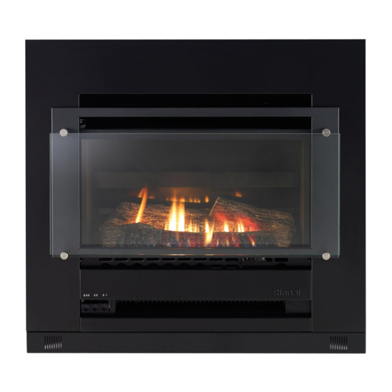
The appliance is fitted within a sheet metal Zero Clearance Box Assembly that has been installed into a wall or other suitable structure. Materials need not be non-combustible. When installed correctly the appliance is a flush to wall mount. APPLIANCE OVERVIEW (1) Rinnai Slimfire Heater. (2) Push button control panel. (a) Ignition / Low button. (b) Medium button. -
Page 10: Operation
In the event of a power failure, turning the heater to its lowest setting may allow the heater to continue operating without overheating. The fan will not work without NOTE electrical power. Rinnai RIBF25 OIM... -
Page 11: Care & Maintenance
Use the following chart to help determine whether a service call is required, however if you are unsure about the way your heater is operating, or if you have any other faults or problems, please refer to your installer or a Rinnai Customer Care Centre Consultant, see back page for Rinnai contact details. -
Page 12: Abnormal Flame Pattern
/ inadequate flue system or the artificial logs/burn media may have shifted from when the heater was first installed. There are some warning signs that could indicate a problem. If any of the signs below occur, please contact Rinnai. NORMAL FLAME PATTERN... -
Page 13: Installation Table Of Contents
Wiring Diagram .................................. 34 Contacts This appliance MUST be installed, maintained and removed ONLY by an Authorised Person. For continued safety of this appliance it MUST be installed and maintained in accordance with WARNING the manufacturers instructions. Rinnai RIBF25 OIM... -
Page 14: General Installation Information
For durability of surfaces you should contact the relevant manufacturer for their specification. RINNAI DOES NOT TAKE ANY RESPONSIBILITY FOR ANY DAMAGE OCCURRING TO ANY ITEMS INSTALLED ABOVE AND IN THE VICINITY OF THE HEATER. -
Page 15: Enclosure Requirements
When preparing a cavity / frame for a zero clearance installation the total cavity depth MUST also include the thickness of the external cladding, as the zero clearance box MUST BE installed flush with the cladding surface. Failure to do this will cause misalignment of the flue systems. Rinnai RIBF25 OIM... -
Page 16: Gas Supply
Rubber Grommet A qualified electrician will need to be consulted where a direct wired installation is required. Any such installation must comply with the requirements of AS/NZS 5601, AS/NZS 3000 and any other relevant local regulations. IMPORTANT Rinnai RIBF25 OIM... -
Page 17: Flueing
The flue system must be fully assembled and secured in place before the heater is installed into the enclosure. Refer to separate Flueing Installation Manual for Rinnai Flamefire heaters. O p ening into a b u il d i n g... -
Page 18: Flue Installation Options
FLUEING FLUE INSTALLATION OPTIONS The following diagrams illustrate the flue installation options that are available for the Slimfire 252 flame. ONLY the genuine Rinnai Flamefire (FLF) flue is certified as part of the Rinnai Slimfire 252 space heaters. WARNING ONLY an authorised person must install, service and remove the Rinnai Slimfire 252 space heater and flue system. -
Page 19: Masonry Flue Installation
MASONRY FLUE INSTALLATION A ‘Lined Chimney’ installation is used when the existing chimney condition is inadequate for an Open Chimney’ installation and uses a Rinnai Flexiliner (flexible) flue system: IMPORTANT FLFHA5FLEX - for heaters Pre 2012 * / FLEXLINER03 - for heaters Post 29/11/12 2012 # Refer to the instruction sheet provided with this kit for installation details. -
Page 20: Engine Installation
(e.g. non combustible insulation or heat resistant silicon). Remove (do not discard) the gas/electrical access plate (D) five screws. Step 4. Positioning the Heater Engine Place the heater engine in front of the fireplace enclosure. Rinnai RIBF25 OIM... - Page 21 (not supplied) using the three holes across the top of the fascia assembly mounting panel and in at least two of the holes on each side of the side panels as shown . Step 10. Completing Heater Installation Go to "Burner Media Installation" on page 25. Rinnai RIBF25 OIM...
-
Page 22: Zero Clearance
Then secure the base panel (I) to the side panels (F) & (G) with four screws (supplied). Ensure flue has been installed as per ‘Flueing Installation Manual For Rinnai Flamefire Heaters’ Flue guide rails screws and pop rivets are supplied with Zero Clearance kit, part number R2520. - Page 23 Secure the zero clearance box into the cavity (K) with appropriate fasteners (not supplied). Install the Rinnai rigid flue system components (L) in accordance with the ‘Flueing Installation Manual For Rinnai Flamefire Heaters’ that is provided with the flue kit.
- Page 24 CAUTION Step 10. Connect Flue Connect flue in accordance with the ‘Flueing Installation Manual For Rinnai Flamefire Heaters’ supplied with flue kit. Step 11. Secure Flue Replace the flue access plate (N) and secure the guide plate (C) of the transition box assembly to the flue access plate (N) with two screws (S) (supplied).
-
Page 25: Burner Media Installation
Ensure that you locate and remove the satchel before discarding the packaging material. IMPORTANT Carefully unpack the log set (G) from the packaging material (F) and inspect for damage. If ANY damage is evident DO NOT continue with installation and contact your supplier for advice. Rinnai RIBF25 OIM... - Page 26 Step 4. Replacing the Burner Box Glass Replace burner box glass panel assembly in reverse sequence as instructed in "Step 1. Removing the Burner Box Glass" on page Step 5. Completing Heater Installation Go to "Commissioning" on page 27. COVERING PORTS Rinnai RIBF25 OIM...
-
Page 27: Commissioning
It is the responsibility of the installer to check that under normal operating conditions of the appliance, all flue gases are exhausted to the outside atmosphere and that there is no spillage of combustion gases into the room. Please refer to AS/NZS 5601. Rinnai RIBF25 OIM... - Page 28 For protection of young children or the infirm a secondary guard is required. Step 4. Check Flame Pattern 4.1 Each Rinnai Flame Fire heater has a distinct flame pattern. Abnormal flame performance and / or pattern can indicate a problem with the heater, such as blocked gas injectors, incorrectly installed / inadequate flue system or the artificial logs/burn media may have shifted from when the heater was first installed.
- Page 29 Be aware that located directly below the downdraft diverter relief opening (A) is the convection air outlet opening (B), when checking for spillage DO NOT test for spillage in this opening. If unsure contact Rinnai for advice. Fascia is not shown in the above two images for reasons of clarity! Step 6.
-
Page 30: Installation Checklist & Record
Is the appliance positioned in a suitable location (clearances, combustible clearances, mantels and surrounds etc.)? 2. Was a Rinnai approved flue system installed and tested in accordance with the instructions? 3. Has the gas pressure checked and set? 4. Has the log set / burn media been installed as per instructions? 5. -
Page 31: Installation Record
Model Number * Serial Number * Installation Address: * This information will need to be copied from the data plate, located on the inside of the appliance. Ensure this Operation and Installation manual is left with the customer. IMPORTANT Rinnai RIBF25 OIM... -
Page 32: Specifications
Combustible Opening (Zero Clearance Box & Twin skinned Flue) Burners Ember bed and flame burner Combustion System Naturally aspirated multi port burner. Can be flued directly into a sealed chimney when fitted with a Rinnai Natural draft. approved flue system. Masonry Flue Type FlexiLiner single skinned, diameter: Ø100 mm. - Page 33 Internal Depth (Excluding Spigot) Internal Depth (Including Spigot) Fascia Depth Total External Depth Gas Connection Centre (from base of appliance) Gas Connection Centre (from right side of appliance) Gas Connection Depth (from front of engine) All dimensions are in mm. Rinnai RIBF25 OIM...
-
Page 34: Wiring Diagram
SPECIFICATIONS WIRING DIAGRAM WIRING DIAGRAM FAN SWITCH HI/ LOW (MICRO) FAN SWITCH ON/OFF (THERMAL) SPARKER ELECTRODE 220~240 v 50 Hz IGN SWITCH (MICRO) PN 10153 BLUE BROWN WHITE GREEN YELLOW OVER HEAT SWITCH SOLENOID VALVE THERMOCOUPLE Rinnai RIBF25 OIM... - Page 35 NOTES Rinnai RIBF25 OIM...
-
Page 36: Contacts
Tel: 1300 555 545* Fax: 1300 555 655 Monday to Friday, 8.00 am to 5.00 pm EST. *Cost of a local call higher from mobile or public phones. For further information visit www.rinnai.com.au or email enquiry@rinnai.com.au innai has a Service and Spare Parts network with...
Need help?
Do you have a question about the Slimfire 252 and is the answer not in the manual?
Questions and answers