Table of Contents

Related Manuals for Rinnai Compact 2 RIBF2L


Summary of Contents for Rinnai Compact 2 RIBF2L
-
Page 1: Installation Guide
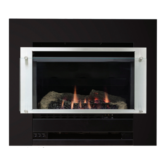
Installation guide Compact 2 Models: RIBF2N/RIBF2L Standard frame Traditional frame Installer, please note: The gas and electrical plate of the unit is not required when attaching the traditional frame, refer p. 18 for further information. - Page 2 Improper installation, adjustment, alteration, service or maintenance can cause property damage, personal injury or loss of life. For more information about buying, using, and servicing of Rinnai appliances call: 0800 RINNAI (0800 746 624). Rinnai New Zealand Limited 105 Pavilion Drive, Mangere, Auckland...
-
Page 3: Table Of Contents
Specification ............ 4 Enclosure dimensions ........5 Clearances ............6 Gas connection ..........8 Electrical connection ........9 Flueing options ..........10 Flueing guidelines ........... 11 Masonry flue installations........ 12 Masonry installation ........14 Inbuilt mock chimney ........16 Completing the heater installation ....18 Flame pattern .......... -
Page 4: Specification
= 9-25 MJ/h 2-speed. Heat is distributed from outer 150 mm. Appliance must be Output = 1.6-5 kW* the top of the appliance. installed with a Rinnai flue system. Efficiency = 73% Energy star = 2.8 stars* Data plate Power consumption and... -
Page 5: Enclosure Dimensions
Enclosure dimensions The main points governing location are flueing and warm air distribution. The enclosure dimensions provided are critical to the installation of this appliance and must be adhered to. The heater must be positioned on a flat level surface that allows free movement of the appliance. -
Page 6: Clearances
Clearances The clearances listed below, measured from the edge of the inner glass, are minimum clearances unless otherwise stated. While the heater is operating The appliance must not be installed where curtains or other combustible materials could come into contact with the heater. The 1000 mm clearance above is the clearance to the ceiling. - Page 7 The below diagrams are to assist people who are determining the clearance area around the Compact 2 without having the unit on site. Compact 2 standard frame 1100 Minimum to ceiling Minimum above fire Clearance Clearance Glass width Compact 2 traditional frame 1100 Minimum to ceiling Minimum above fire...
-
Page 8: Gas Connection
Gas connection Gas pipe sizing must consider the gas input to this appliance, as well as other gas appliances in the building. The gas supply termination is inside the heater, and enters from the rear of the appliance. The length of the gas supply ½... -
Page 9: Electrical Connection
Electrical connection If a power point is used it must be 230 V, rated 10 A, and must be earthed. The power point MUST NOT be located above the heater. Alternatively the appliance can be direct wired if the power supply is to be concealed. The Compact 2 is fitted with a 1.5 m power cord. -
Page 10: Flueing Options
Masonry installations Rinnai recommends the use of a flexiliner flue (Ø 100 mm) as it ensures optimum performance of the appliance. Installation without a flexiliner flue is permitted as long as the chimney has been swept, checked for soundness and ability to achieve a good draw. -
Page 11: Flueing Guidelines
Flueing guidelines Flashings to to the top of the chimney structure do not form part of the flue kit and must be specified. Inner flue: Clearance to combustibles Clearance from the inner flue to a combustible material must be greater than 25 mm. Flue cowl clearance To ensure products of combustion are cleared, adequate clearance for the building is required. -
Page 12: Masonry Flue Installations
Some criteria for checking chimney soundness Rinnai strongly recommends the use of a Rinnai flexiliner flue system. Failure to meet this criteria may result in an unsafe situation. Installation without a flexiliner flue is permissible as long as the chimney is swept, checked for soundness and ability to achieve a good draw. - Page 13 Installation Installation, servicing and repair shall be carried out only by authorised personnel.
-
Page 14: Masonry Installation
Masonry installation Adapt instructions as necessary for masonry installations without a flexiliner flue. 1. Prepare site: Ensure the between the heater and the 8. Insert unit into fireplace: enclosure meets the dimension fireplace brickwork. If an Carefully move the heater into requirements and check the adequate seal cannot be formed the fireplace ensuring the gas... - Page 15 Fixings R1760-2 Chimney cowl 100 mm stainless steel Guide rails R1760-3 Flexi flue chimney flashing plate (400 x 300 mm) R1760-4 Aluminium flexi flue 3.6 m Guide plate Flexi flue spigot adaptor Attaching the flexiliner flue to the unit 1. Attach the guide rails to the heater using the predrilled holes and four screws. 2.
-
Page 16: Inbuilt Mock Chimney
Inbuilt mock chimney (zero clearance installation) 8. Connect flue adaptor: 15. Secure heater: Fasten the 1. Prepare site: Ensure the enclosure meets the dimension Connect the flue adaptor* to heater to the cladding using requirements and check the the engine by aligning the guide appropriate fasteners (not gas and electrical supplies have rails with the guide plate* of... - Page 17 2. Assemble the zero clearance box 3. Fit zero clearance box 6. Prepare heater engine 7. Fit cladding Guide rails Flue access plate Gas/electrical access plate 8. Connect flue adaptor 13. Secure flue Flue acccess plate Flue adaptor Guide rails 15.
-
Page 18: Completing The Heater Installation
Completing the heater installation 7. Attach frame assembly 1. Remove combustion Carefully place (do not pour) chamber glass the granules over and around Re-attach the gas/electrical Loosen, but do not remove the the front burner ports. It is plate. DO NOT do this if you are bottom two retaining screws. - Page 19 1. Removing the combustion chamber glass panel 1. Install log set and granules Retaining screw Retaining screw Front feet as Glass clamp pivot points 6. Check burner pressures 7. Attach frame assembly Top fold Rear view of installed frame Test point screw Frame assy mounting tabs Regulator...
-
Page 20: Flame Pattern
If the appliance cannot be made to perform correctly please contact Rinnai. 20 | Compact 2 Installation Guide: 11817-D 04-15... -
Page 21: Wiring Diagram
Wiring diagram (10153) FAN S WITC H HI/ LOW (MIC R O) ( +) ( - ) FAN S WITC H ON/OFF (T HE R MAL) S PAR KE R E LE CTR ODE 220~240 v 50 Hz IGN S WITC H G /Y (MIC R O) Blue... -
Page 22: Appendix 1
Appendix 1 Zero clearance installation overview We have this final installation image available for a zero clearance installation. It is intended to provide an overview of how all the components are fitted together and to illustrate important installation points. Flue installed and independently supported Flue adaptor connected... - Page 24 Experience our innovation Rinnai.co.nz 0800 746 624 http://www.youtube.com/rinnainz Compact 2 installation guide 11817-D 04-15...
Need help?
Do you have a question about the Compact 2 RIBF2L and is the answer not in the manual?
Questions and answers