
Related Manuals for Raymarine HYPERVISION HV-100


Summary of Contents for Raymarine HYPERVISION HV-100
- Page 1 HYPERVISION HV-100 Installation instructions English (en-US) Date: 09-2019 Document number: 87362-3 © 2019 Raymarine UK Limited...
- Page 3 Software updates Check the Raymarine website for the latest software releases for your product. www.raymarine.com/software Product documentation The latest versions of all English and translated documents are available to download in PDF format from the website: www.raymarine.com/manuals.
-
Page 5: Table Of Contents
Contents Chapter 1 Important information..................7 Water ingress ..........................7 Disclaimer ........................... 8 Declaration of conformity......................8 Warranty registration ......................... 8 Product disposal ........................8 IMO and SOLAS ......................... 8 Technical accuracy ........................8 Chapter 2 Document and product information.............11 2.1 Product documentation...................... 12 Operation instructions ...................... - Page 6 6.1 Routine checks ........................42 6.2 Transducer cleaning ......................42 6.3 Re-applying anti-fouling paint..................42 Chapter 7 Technical support..................43 7.1 Raymarine product support and servicing ..............44 7.2 Learning resources ......................45 Chapter 8 Technical specification................. 47 8.1 Technical specification ...................... 48 Physical specification......................48...
-
Page 7: Chapter 1 Important Information
Although the waterproof rating capacity of this product meets the stated water ingress protection Technical Specification standard (refer to the product’s ), water intrusion and subsequent equipment failure may occur if the product is subjected to high-pressure washing. Raymarine will not warrant products subjected to high-pressure washing. Important information... -
Page 8: Disclaimer
Raymarine. Raymarine is not responsible for damages or injuries caused by your use or inability to use the product, by the interaction of the product with products manufactured by others, or by errors in information utilized by the product supplied by third parties. - Page 9 As a result, Raymarine cannot accept liability for any differences between the product and this document. Please check the Raymarine website (www.raymarine.com) to ensure you have the most up-to-date version(s) of the documentation for your product. Important information...
-
Page 11: Chapter 2 Document And Product Information
Chapter 2: Document and product information Chapter contents • 2.1 Product documentation on page 12 • 2.2 Applicable products on page 12 • 2.3 Required additional components on page 13 • 2.4 Parts supplied on page 14 Document and product information... -
Page 12: Product Documentation
Display software Ensure your display software is updated to the latest version. To updated your display software refer to the operations instructions for your display. For the latest software for your display refer to the Raymarine website: www.raymarine.com/software Document illustrations Your product and if applicable, its user interface may differ slightly from that shown in the illustrations in this document, depending on product variant and date of manufacture. -
Page 13: Product Overview
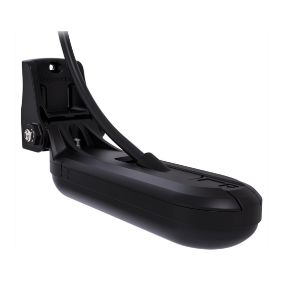
Product overview The HV-100 is a HyperVision™ transom mount plastic transducer. The transducer is compatible with HyperVision™ variant displays. HyperVision™ transducers are capable of producing sonar images for: • RealVision™ 3D (Hyper 1.2 MHz) • RealVision™ 3D (Standard 350 kHz) •... -
Page 14: Compatible Displays (Hv Variants)
Compatible displays (HV variants) Compatible displays are listed below. Part number Description E70532 Element™ 7 HV E70534 Element™ 9 HV E70536 Element™ 12 HV 2.4 Parts supplied The following parts are supplied with your product: Unpack your product carefully to prevent damage or loss of parts. Check the box contents against the list below. - Page 15 Transom bracket 3 x bracket fixing screws (4.2x19 mm A4 stainless steel) M5x10 hex bolt (A4 stainless steel) M5 washer (A4 stainless steel) Hanger bracket Escutcheon plate (used when routing cable through transom or a bulkhead) 2 x adjustment slot washers Transducer with 6 m (19.69 ft) fitted cable 4 x escutcheon plate fixings (#8x13 SUS316) 3 x cable clips...
-
Page 17: Chapter 3 Installation
Chapter 3: Installation Chapter contents • 3.1 Tools required on page 18 • 3.2 Pre-installation test on page 19 • 3.3 Selecting a location on page 20 • 3.4 Mounting on page 24 Installation... -
Page 18: Tools Required
3.1 Tools required The following tools are required to install your transducer: Power drill 2. 4 mm hex wrench (Allen key) 3. 5 mm hex wrench (Allen key) 4. Pozi-drive screw driver 5. Drill bit (suitable for pilot holes) 6. Marine grade sealant 24 mm (15/16 in) or suitable size hole cutter (only required when routing the cable through a bulkhead or transom) 8. -
Page 19: Pre-Installation Test
> Transducer). 6. Check that accurate depth and temperature readings are displayed. 7. If you experience difficulties obtaining readings then contact Raymarine Technical Support. Warning: Transducer operation Only test and operate the transducer in the water. Do NOT operate out of water as overheating may occur. -
Page 20: Selecting A Location
3.3 Selecting a location Warnings and cautions Important: Before proceeding, ensure that you have read and understood the warnings and cautions provided in the Chapter 1 Important information section of this document. Location requirements The guidelines below should be followed when selecting a location for the transducer. Note: The information below is provided for guidance only. - Page 21 Note: The illustration above provides potential transducer locations for the hull types depicted. Before selecting a location ensure that all of the location requirements have been met. • The transducer should be mounted a minimum of 380 mm (15 in) away from the propeller. For clockwise rotating propellers, mount the transducer on the starboard side, for counter-clockwise, mount on the port side.
-
Page 22: Transducer Angle Requirements
Tilting the transducer upwards is not recommended as this can cause aeration across the transducer face. EMC installation guidelines Raymarine equipment and accessories conform to the appropriate Electromagnetic Compatibility (EMC) regulations, to minimize electromagnetic interference between equipment and minimize the effect such interference could have on the performance of your system Correct installation is required to ensure that EMC performance is not compromised. -
Page 23: Hv-100 Product Dimensions
• Raymarine specified cables are used. • Cables are not cut or extended, unless doing so is detailed in the installation manual. Note: Where constraints on the installation prevent any of the above recommendations, always ensure the maximum possible separation between different items of electrical equipment, to provide the best conditions for EMC performance throughout the installation. -
Page 24: Mounting
3.4 Mounting Transducer assembly Follow the steps below to assemble the transducer ready for attaching to the Transom bracket. 1. Slide the hanger bracket over the top of the transducer until the notch in the side of the bracket hanger aligns with the unlocked symbol on the side of the transducer. 2. -
Page 25: Mounting The Transom Bracket
Ensure tightening torque does not exceed 2 N·m (1.48 lbf·ft). Overtightening may cause damage to the transducer. Mounting the transom bracket The transducer must be mounted at a height where the transducer will be submerged whilst the vessel is planing and turning. The steps below describe the initial mounting steps required in order to test your transducer’s performance. -
Page 26: Mounting The Transducer Assembly
Note: The third locking screw is not used until the transducer has been successfully tested. Mounting the transducer assembly Important: • Only perform the installation with your vessel out of the water. • Do NOT lift or suspend the transducer using its cable. - Page 27 • Do NOT overtighten the bolt. Overtightening may cause damage to the transducer. 1. Position the transducer assembly in the transom bracket, ensuring that the ratchet grooves in the transom bracket are aligned with the ratchet grooves in the hanger bracket. 2.
-
Page 28: Mounting The Escutcheon Plate
Mounting the escutcheon plate Your transducer is supplied with an escutcheon plate. If you have chosen to route the transducer cable through the transom or through a bulkhead, you can use the supplied escutcheon plate to cover the hole required to accommodate the cable. The plate is designed to fit over a hole up to 25 mm (1 inch) in diameter. -
Page 29: Finalizing The Transducer Mounting
i. Loosen the mounting bolt to adjust the transducer angle. Angle adjustment ii. Loosen the 2 mounting bracket screws to adjust the transducer height. Height adjustment iii. Re-tighten the mounting bolt and mounting screws before re-testing. Important: • It may be necessary to make several adjustments to the transducer before obtaining optimum performance. - Page 30 1. Drill the locking hole location taking care not to damage the transom bracket. 2. Fill the locking hole with marine grade sealant. 3. Lock the transducer position by fully tightening all 3 transom bracket mounting screws. 4. Lock the transducer angle by tightening the mounting bolt; do not exceed a torque of 4 N·m (2.95 lbf·ft).
- Page 31 The anti-fouling paint should be applied in a thin and even coat covering all externally exposed transducer surfaces. You should clean your transducer regularly and re-apply anti-fouling paint every 6 months, or sooner depending on how rapidly organic growth builds up. For guidance on transducer cleaning refer to p.42 —...
-
Page 33: Chapter 4 Connections
Chapter 4: Connections Chapter contents • 4.1 General cabling guidance on page 34 • 4.2 Cable routing on page 34 • 4.3 Making connections on page 35 Connections... -
Page 34: General Cabling Guidance
• Unless otherwise stated only use cables supplied by Raymarine. • Where it is necessary to use non-Raymarine cables, ensure that they are of correct quality and gauge for their intended purpose. (e.g.: longer power cable runs may require larger wire gauges to minimize voltage drop along the run). -
Page 35: Making Connections
4.3 Making connections Follow the steps below to connect the cable(s) to your product. 1. Ensure that the vessel's power supply is switched off. 2. Ensure that the device being connected to the unit has been installed in accordance with the installation instructions supplied with that device. -
Page 37: Chapter 5 System Checks And Troubleshooting
Chapter 5: System checks and troubleshooting Chapter contents • 5.1 Operation instructions on page 38 • 5.2 Troubleshooting on page 38 • 5.3 Sonar troubleshooting on page 39 System checks and troubleshooting... -
Page 38: Operation Instructions
If after referring to this section you are still having problems with your product, please refer to the Technical support section of this manual for useful links and Raymarine Product Support contact details. -
Page 39: Sonar Troubleshooting
Possible solutions Incorrect display software version Display software may be incompatible with your connected transducer. Check the Raymarine website and ensure that the display is running the latest available software. Transducer not connected Connect compatible transducer / Ensure that the transducer cable connector is fully inserted and locked in position and reboot the display. -
Page 40: Resetting The Sonar
Possible causes Possible solutions Damaged transducer or cable Check that the transducer cable connector is free from damage, is correctly orientated and fully inserted into the display and that the connector is locked in position. If damage is detected, replace the transducer. 2. -
Page 41: Chapter 6 Maintenance
Chapter 6: Maintenance Chapter contents • 6.1 Routine checks on page 42 • 6.2 Transducer cleaning on page 42 • 6.3 Re-applying anti-fouling paint on page 42 Maintenance... -
Page 42: Routine Checks
6.1 Routine checks The following periodic checks should be made: • Examine cables for signs of damage, such as chafing, cuts or nicks. • Check that the cable connectors are firmly attached and that their locking mechanisms are properly engaged. Note: Cable checks should be carried out with the power supply switched off. -
Page 43: Chapter 7 Technical Support
Chapter 7: Technical support Chapter contents • 7.1 Raymarine product support and servicing on page 44 • 7.2 Learning resources on page 45 Technical support... -
Page 44: Raymarine Product Support And Servicing
You can obtain this product information using diagnostic pages of the connected MFD. Servicing and warranty Raymarine offers dedicated service departments for warranty, service, and repairs. Don’t forget to visit the Raymarine website to register your product for extended warranty benefits: http://www.raymarine.co.uk/display/?id=788. Contact Region •... -
Page 45: Learning Resources
(Authorized Raymarine distributor) • Tel: +7 495 788 0508 7.2 Learning resources Raymarine has produced a range of learning resources to help you get the most out of your products. Video tutorials Raymarine official channel on YouTube: • YouTube LightHouse™... -
Page 47: Chapter 8 Technical Specification
Chapter 8: Technical specification Chapter contents • 8.1 Technical specification on page 48 Technical specification... -
Page 48: Technical Specification
8.1 Technical specification Physical specification Overall dimensions: • Length: 224.99 mm (8.86 in) • Height: 112.69 mm (4.44 in) • Width: 76.00 mm (2.99 in) Cable length: • HV-100: 6 m (19.69 ft) fitted cable Weight (unboxed): 1.05 kg (2.31 lb) Environmental specification Operating temperature range: –2ºC (28.4ºF) to + 55ºC (131ºF) -
Page 49: Conformance Specification
Conformance specification Conformance • EN 60945:2002 • IEC 28846:1993 • EMC Directive 2014/30/EU • Australia and New Zealand: C-Tick, Compliance Level 2 Technical specification... -
Page 51: Chapter 9 Spares And Accessories
Chapter 9: Spares and accessories Chapter contents • 9.1 Spares on page 52 • 9.2 Accessories on page 52 Spares and accessories... -
Page 52: Spares
9.1 Spares Description Part number HV-100 Transom bracket R70651 9.2 Accessories Description Part number HV-100 trolling motor mount A80557 HyperVision™ transducer extension cable 4 m A80562 (13.12 ft) - Page 55 Index LightHouse Sport Compatible displays ..........14 Location requirements General ............... 20 Accessories .............52 Anti-fouling ..........18, 30, 42 Assembly ..............24 Maintenance.............. 7 Bend radius .............23 Bracket mounting ............25 Operation instructions ........12, 38 Cable Parts supplied............14 extension ............. 34 Product dimensions..........23 Protection ............
- Page 58 FLIR Belgium BVBA Luxemburgstraat 2, 2321 Meer. Belgium. Tel: +44 (0)1329 246 700 www.raymarine.com a brand by...
Need help?
Do you have a question about the HYPERVISION HV-100 and is the answer not in the manual?
Questions and answers