Table of Contents
Advertisement
Quick Links
Advertisement
Table of Contents

Subscribe to Our Youtube Channel
Related Manuals for Insportline 19986


Summary of Contents for Insportline 19986
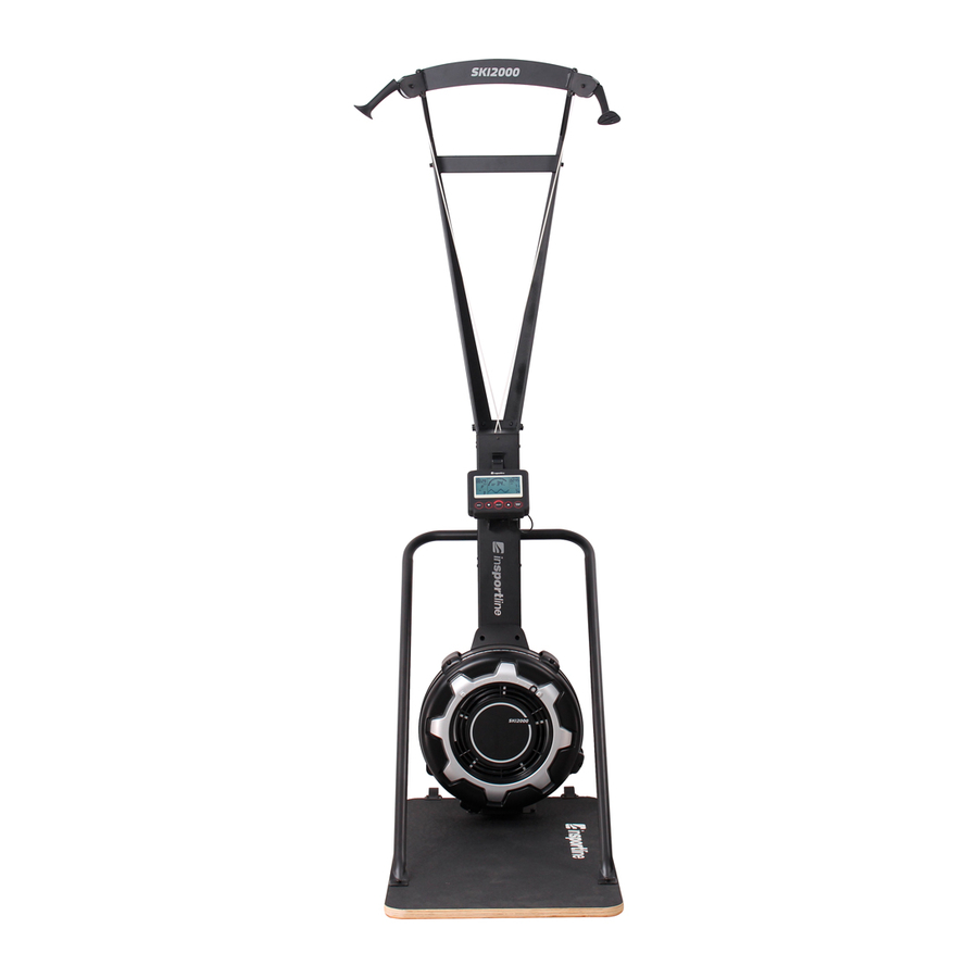
- Page 1 USER MANUAL – EN IN 19986 Cross-country trainer inSPORTline SKI2000...
-
Page 2: Table Of Contents
CONTENTS SAFETY INSTRUCTIONS ........................3 CROSS-COUNTRY TRAINER – FREE STANDING ................3 PRODUCT DESCRIPTION ........................3 ASSEMBLY ............................. 4 CROSS-COUNTRY TRAINER – WALL MOUNTING ................13 PRODUCT DESCRIPTION ........................13 ASSEMBLY ............................13 CONSOLE ............................. 22 BUTTONS ............................22 DISPLAY ............................23 PROGRAMS ............................ -
Page 3: Safety Instructions
SAFETY INSTRUCTIONS • Read the manual carefully and keep it for future reference. • Keep the distance from another object at least 0,6 m. • Adjustable parts can not prohibit the movement of the user. • Do not modify the product. •... -
Page 4: Assembly
16. Wooden base ASSEMBLY TOOLS Tools are included. Allen key 6 mm Screwdriver Allen key 5 mm Wrench ASSEMBLY MATERIAL Picture Description Qty. Allen screw M8x75 mm Flat washer M8 Nut M8 Screw M8x12 mm Screw M8x15 mm Allen screw 6 mm Wrench Wall mounting Screw ST8x50 mm... - Page 5 Arc washer M8 Allen screw M8x30 mm Flat washer M8 Allen key 5 mm STEP 1 Remove top frame (4) and main frame (1). NOTE: Be careful with covers Do not throw away the packaging material immediately but dispose of it only after finishing the assembly.
- Page 6 STEP 2 Connect the Left/Right support arm (2/3) to the main frame (1) with 4 screws (86) and washers (71). Tighten them. STEP 3 Connect the connection rod (5) to the Left/Right support arm (2/3) with 2 screws (87) and washers (71).
- Page 7 STEP 4 Connect top frame (4) to the Left/Right support arm (2/3) with 4 screws (86) and washers (71). Tighten them. NOTE: Check if the Drive cord (52) is untangled.
- Page 8 STEP 5 Stand up the construction. Tighten Left/Right support arm (2/3) with screws (86) and washer (71). Tighten them. STEP 6 Remove the clicker from the drive cord (52).
- Page 9 STEP 7 Connect the mobile holder (15) to the console (14) with rubber band (34) STEP 8 Connect the console (14) to the console holder on the main frame (1) with 1 screw (82), washer (71) a nut (72). STEP 9 Connect the sensor cable (17) to the console (14a)
- Page 10 STEP 10 Connect the main frame (1) to the wooden base (18) with 4 screws (83) and flat washers (71)
- Page 11 STEP 11 Connect the support rod (14) to the main frame (1) with 2 screws (84), washers (85) and bracket cushion (42).
- Page 12 STEP 12 Connect the support rod (6) to the wooden base (18) with 2 screws (83) and washers (71). Tighten them.
-
Page 13: Cross-Country Trainer - Wall Mounting
CROSS-COUNTRY TRAINER – WALL MOUNTING PRODUCT DESCRIPTION 1. Handle 2. Connection rod 3. Cable 4. Left support arm 5. Main frame 6. Console 7. Back fan cover 8. Front fan cover 9. Damper 10. Damper cover 11. Top support rod 12. - Page 14 Screw ST8x50 mm Screw M8x35 mm Nut M8 Screw M8x12 mm Screw M8x15 mm Flat washer M8 Flat washer Φ22xΦ9x2.0 mm Allen key 6 mm Wrench 13-15 STEP 1 Remove top frame (4) and main frame (1). NOTE: Be careful with covers Do not throw away the packaging material immediately but dispose of it only after finishing the assembly.
- Page 16 STEP 2 Connect the Left/Right support arm (2/3) to the main frame (1) with 4 screws (86) and washers (71). Tighten them. STEP 3 Connect the connection rod (5) to the Left/Right support arm (2/3) with 2 screws (87) and washers (71).
- Page 17 STEP 4 Connect top frame (4) to the Left/Right support arm (2/3) with 4 screws (86) and washers (71). Tighten them. NOTE: Check if the Drive cord (52) is untangled.
- Page 18 STEP 5 Stand up the construction. Tighten Left/Right support arm (2/3) with screws (86) and washer (71). Tighten them. STEP 6 Remove the clicker from the drive cord (52).
- Page 19 STEP 7 Connect the mobile holder (15) to the console (14) with rubber band (34) STEP 8 Connect the console (14) to the console holder on the main frame (1) with 1 screw (82), washer (71) a nut (72). STEP 9 Connect the sensor cable (17) to the console (14a)
- Page 20 KROK 10 Connect the wall mounting – bottom (8) to the main frame (1) with 2 screws M8x35 mm and flat washer (71). KROK 11 Remove one screw (87) and washer (71) from left support arm (2). Connect wall mounting - top (9) with the same screw and washer.
- Page 21 KROK 13 Place the machine against a solid wall. Make 4 marks at the location where the machine will be attached (8 and 9). Drill 4 holes at the holes. KROK 14 Fasten to the wall with 4 screws (54) and washers (55). WARNING: Use the screws according to the type of wall to which you want to attach the device.
-
Page 22: Console
CONSOLE The device uses a fan assembly to create resistance. We recommend using the console mainly to compare the results and track your progress. GENERAL INFORMATION Turn on: Move the handles to start the Quick start program or press any button to switch the console to standby. -
Page 23: Display
Press the button after finishing the program to return to main menu. ENTER/STOP Choose selected program Hold the button for 3 seconds to reset all values and console. If the display backlight is off during exercise, press to turn on the backlight, press again to pause the program, and press again to start the program. -
Page 24: Programs
CALORIES & CAL/HOUR • Display burned calories from 0 to 999 cal. • Flashing 10, means that the countdown program can be set from 10 to 990 cal. • CAL/HOUR displays number of calories burned per hour. CYCLE & WATTS •... -
Page 25: Use
20/10 INTERVAL PROGRAM On display will be flashing 8 for number of repetitions. 20 stands for 20 seconds of exercise and 10 stands for 10 seconds of rest. User can adjust the number of repetitions with UP a DOWN buttons from 1 to 99. -
Page 26: Double-Pole Technique
• Do not twist or cross ropes and avoid pulling the ropes to the point where they stop. • Do not release the handles while they are in the extended position. Return the handles to the upper position before releasing them. •... -
Page 27: Classic Cross-Country Technique (Arm Center)
CLASSIC CROSS-COUNTRY TECHNIQUE (ARM CENTER) Start with one hand raised slightly bent. Pull the upper arm down while gradually raising the lower arm. Continue to alternate the shoulders and hold several bends in one arm, as this is a stronger position. RESISTANCE The fan (32) has inbuild dampener (31) for resistance change. -
Page 28: Storage
• Check the condition of the drive cord. Replace the drive cord if it is damaged or broken. • Maintenance and operation of the machine is the responsibility of the machine owner. • Damaged or worn parts must be replaced immediately. Until then, the device must not be used. -
Page 29: Diagram - Free Standing
DIAGRAM – FREE STANDING... -
Page 30: Parts List - Free Standing
PARTS LIST – FREE STANDING Name Qty. Name Qty. Main frame Damper Cap Left support arm Pulley Cover Right support arm Pulley Holder Top frame Body upper cover Connection rod Washer Support Generator Base Transport wheels cover Handle Body Cover (L/R) Handle Plug Short Spacer Perforated Steel Mesh... - Page 31 Screw ST4.2x13 mm Screw M8x12mm Screw ST3.5x12 mm Screw M8x15mm Washer Φ12xΦ3.5x1.0 mm Wrench Screw M5x8 mm Allen key 6 mm Nut M8 Allen key 5 mm Screw ST4.2x16 mm EVA Single Glue Screw M8x75 mm Rubber Cushion Screw M8x30 mm Screw M5x8 mm Screw M8x50 mm Screw M4x12mm...
-
Page 32: Diagram - Wall Mounted
DIAGRAM – WALL MOUNTED... -
Page 33: Parts List - Wall Assembly
PARTS LIST – WALL ASSEMBLY Name Qty. Name Qty. Main frame Damper Cap Left support arm Pulley Cover Right support arm Pulley Holder Top frame Body upper cover Connection rod Generator Base Lower Wall Mounting Bracket Handle Upper Wall Mounting Bracket Handle Plug Body Cover (L/R) Short Spacer... -
Page 34: Environment Protection
Screw M5x8 mm Allen key 6 mm Nut M8 EVA Single Glue Screw ST4.2x16 mm Rubber Cushion Screw M8x75 mm Screw M5x8 mm Screw M8x12mm Screw M4x12mm Screw M8x15mm Wrench ENVIRONMENT PROTECTION After the product lifespan expired or if the possible repairing is uneconomic, dispose it according to the local laws and environmentally friendly in the nearest scrapyard. - Page 35 • User’s fault, i.e. product damage caused by unqualified repair work, improper assembly, insufficient insertion of seat post into frame, insufficient tightening of pedals and cranks • Improper maintenance • Mechanical damages • Regular use (e.g. wearing out of rubber and plastic parts, moving mechanisms, joints, wear of brake pads/blocks, chain, tires, cassette/multi wheel etc.) •...
Need help?
Do you have a question about the 19986 and is the answer not in the manual?
Questions and answers