
Related Manuals for SMC Networks FH100 Series


Summary of Contents for SMC Networks FH100 Series
- Page 1 1 / 17 FGX-OM-F001-A PRODUCT NAME Return Filter MODEL / Series / Product Number FH100 Series FH100 X0 Series...
-
Page 2: Table Of Contents
2 / 17 FGX-OM-F001-A Contents ●Safety Instructions 1.How to Order 2.Construction and names of individual parts 3.Specifications 4.Installation and Piping 5.Maintenance 6.Maintenance parts... - Page 3 / 17 FGX-OM-F001 F001-A Return Filter Return Filter Return Filter Safety Safety Safety Instructions Instructions Instructions Instructions These safety instructions are intended to prevent hazardous situations and/or equipment damage. These safety instructions are intended to prevent hazardous situations and/or equipment damage. These safety instructions are intended to prevent hazardous situations and/or equipment damage.
-
Page 4: Safety Instructions
/ 17 FGX-OM-F001 F001-A Return Filter Return Filter Return Filter Safety Instructions Safety Instructions Safety Instructions Safety Instructions Safety Instructions Safety Instructions Caution Caution The product is provided for use in manufacturing industries. The product is provided for use in manufacturing industries. The product is provided for use in manufacturing industries. - Page 5 5 / 17 FGX-OM-F001-A Caution SMC products are not intended for use as instruments for legal metrology. For products that SMC manufactures or sells are not measurement instruments that are qualified by pattern approval tests relating to the measurement laws of each country. Therefore, SMC products cannot be used for business or certification ordained by the measurement laws of each country.
- Page 6 / 17 FGX-OM-F001 F001-A Return Filter Return Filter Return Filter/ /Safety Instructions Safety Instructions Safety Instructions Safety Instructions Be sure to read this before handling the products. Be sure to read this before handling the products. Be sure to read this before handling the products. Be sure to read this before handling the products.
- Page 7 7 / 17 FGX-OM-F001-A Design and Installation Caution 【 Design 】 1. Design the system with operating conditions, including operating pressure, operating temperature, operating fluid, and operating environment appropriate for safe operation. 2. Install the mist separator and micro-mist separator in a place where pulsation seldom occurs. 3.
- Page 8 8 / 17 FGX-OM-F001-A Return Filter/Safety Instructions Be sure to read this before handling the products. These safety instructions are intended to prevent hazardous situations and/or equipment damage. Make sure to follow every instruction since they are for safety. Replacement of element Caution 1.
-
Page 9: How To Order
9 / 17 FGX-OM-F001-A How to Order FH100 - 06 - 0 0 0 - P 005 Table1-7 Made to Order Symbol Made to Order None (Standard) Table1-5 Element Non-standard Symbol Element filtration equipped Paper Micromesh Note) The non-standard filtration is for micromesh elements only. -
Page 10: Construction And Names Of Individual Parts
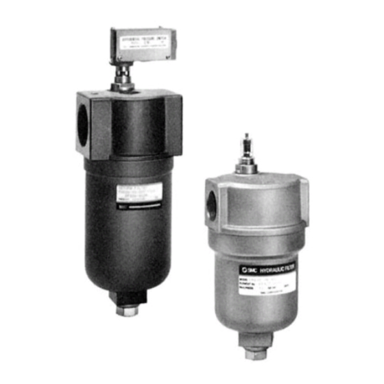
10 / 17 FGX-OM-F001-A 2. Construction and names of individual parts Figure 2-2 (5) Differential pressure indicator Differential Reset button pressure Differential indication switch pressure Blanking cap View port indicator View port 【Differential pressure indicator】 1. When the differential pressure increases to 0.13Mpa (guideline replacement) -
Page 11: Specifications
11 / 17 FGX-OM-F001-A 3. Specifications Table3-1 Specifications Item Specifications Hydraulic fluid: Oils below are applicable. (Note1) Fluid (Petroleum,Water-glycol, Emulsion,Phosphoric ester) Applicable model FH100-06 FH100-08 FH100-10 FH100-12 FH100-16 FH100-20 FH100-24 IN・OUT Port size 1 1/4 1 1/2 2 1/2 (Rc) Drain port size M16×2 Rated flow... -
Page 12: Installation And Piping
12 / / 17 FGX-OM-F001 F001-A 4. Installation and Piping 4. Installation and Piping 4. Installation and Piping 4. Installation and Piping 1) Installation Installation (Refer to 6. Maintenance parts (5) Maintenance (Refer to 6. Maintenance parts (5) Maintenance (Refer to 6. Maintenance parts (5) Maintenance (Refer to 6. -
Page 13: Maintenance
13 / 17 FGX-OM-F001-A 5. Maintenance Replace the element when differential pressure reaches 0.13MPa (red part appears in the view port of the differential pressure indicator or when the differential pressure indicator switch is actuated). Replacement of element should be performed according to the procedure below. 1) Removal of the bowl 1. -
Page 14: Maintenance Parts
14 / 17 FGX-OM-F001-A 6. Maintenance parts [1]Replacement Element Table6-1 3) Element number Element type Port size Element Size Symbol (mm) Paper Micromesh 06,08 EP420-□□ EM810-□□ ø64×L95 EP020-□□ 10,12 EM910-□□ ø 74×L117 EP520-□□ EM020-□□ ø 88×L158 EP620-□□ 20,24 EM120-□□ ø 119×L208 Note) Refer to the Figure 2-1 for the assembly position. - Page 15 15 / 17 FGX-OM-F001-A [2] Replacement Differential pressure indicator Table 6-5 5. Replacement Differential pressure indicator Hydraulic fluid type Name Petroleum Water-glycol, Emulsion Phosphoric ester Differential pressure indication CB-50H CB-50H-V Differential pressure indication CB-51H CB-51H-V switch Blanking cap AG-12H AG-12H-W AG-12H-V Note 1) Refer to the Figure 2-1 for the assembly position.
- Page 16 16 / 17 FGX-OM-F001-A [4] Microswitch for Differential Pressure Indication Switch (1) Contact specifications (4) Electric circuit Table 6-8 Contact specifications Item Specifications Inrush Normally closed Max. 15A current Normally open (N. C. and N. O. common) Minimum applicable load DC5V 160mA Precautions 1.
- Page 17 17 / 17 FGX-OM-F001-A Revision history Revision A: Full scale revision 4-14-1, Sotokanda, Chiyoda-ku, Tokyo 101-0021 JAPAN Tel: + 81 3 5207 8249 Fax: +81 3 5298 5362 http://www.smcworld.com NOTE: Specifications are subject to change without prior notice and any obligation on the part of the manufacturer. ©...
Need help?
Do you have a question about the FH100 Series and is the answer not in the manual?
Questions and answers