Table of Contents
Advertisement
Quick Links
Doc. No. AF∗-OMQ0004-D
PRODUCT NAME
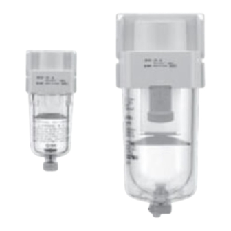
AIR FILTER
MODEL / Series / Product Number
AF10-M5(C)(-2,6,R,Z)-A
AF20-(F,N)01~(F,N)02(B,C)(-2,6,C,J,R,Z)-A
AF30-(F,N)02~(F,N)03(B,C,D)(-2,6,8,J,R,W,Z)-A
AF40-(F,N)02~(F,N)04(B,C,D)(-2,6,8,J,R,W,Z)-A
AF40-(F,N)06(B,C,D)(-2,6,8,J,R,W,Z)-A
AF50-(F,N)06~(F,N)10(B)(-2,6,8,J,R,W,Z)-A
AF60-(F,N)10(B)(-2,6,8,J,R,W,Z)-A
Advertisement
Table of Contents

Related Manuals for SMC Networks AF10-A Series


Summary of Contents for SMC Networks AF10-A Series
- Page 1 Doc. No. AF∗-OMQ0004-D PRODUCT NAME AIR FILTER MODEL / Series / Product Number AF10-M5(C)(-2,6,R,Z)-A AF20-(F,N)01~(F,N)02(B,C)(-2,6,C,J,R,Z)-A AF30-(F,N)02~(F,N)03(B,C,D)(-2,6,8,J,R,W,Z)-A AF40-(F,N)02~(F,N)04(B,C,D)(-2,6,8,J,R,W,Z)-A AF40-(F,N)06(B,C,D)(-2,6,8,J,R,W,Z)-A AF50-(F,N)06~(F,N)10(B)(-2,6,8,J,R,W,Z)-A AF60-(F,N)10(B)(-2,6,8,J,R,W,Z)-A...
-
Page 2: Table Of Contents
Contents Page 1. SAFETY INSTRUCTIONS 2. APPLICATION 3. SPECIFICATIONS 4. HOW TO ORDER 5. OPTIONAL BRACKET ASSEMBLY 6. TROUBLESHOOTING 7. CONSTRUCTION / PARTS LIST 8. SPECIFICATIONS OF BOWL ASSEMBLY 11-19 9. REPLACEMENT PROCEDURE 20-27 10. DISASSEMBLY DRAWING 28-29 11. DIMENSIONS... -
Page 3: Safety Instructions
Safety Instructions These safety instructions are intended to prevent hazardous situations and/or equipment damage. These instructions indicate the level of potential hazard with the labels of “Caution,” “Warning” or “Danger.” They are all important notes for safety and must be followed in addition to International Standards (ISO/IEC) , and other safety regulations. -
Page 4: Limited Warranty And Disclaimer/Compliance Requirements
Safety Instructions Caution We develop, design, and manufacture our products to be used for automatic control equipment, and provide them for peaceful use in manufacturing industries. Use in non-manufacturing industries is not covered. Products we manufacture and sell cannot be used for the purpose of transactions or certification specified in the Measurement Act. - Page 5 Precautions for design ! WARNING ① If no leakage is allowed due to the environment, it cannot be used. Or operating fluid is not air, it cannot be used. ② External parts including the handle (Material: polyacetal) and bowl (Material: polyacarbonate) are made of resin.
-
Page 6: Installation
! CAUTION ① AD17-A and AD27-A with auto drain may leak during exhaust of pressure. (This leakage is allowed in their constructions and not failure.) Be sure to connect piping for drain. Selection ! WARNING ① Grease used on the internal sliding parts and seals may flow to the outlet side. ②... -
Page 7: Air Source
⑥ The piping for drain from auto drain should be connected under the following requirements to avoid operating failure. AD17-A, AD27-A: I.D. φ2.5 (φ3/32") at min., Length 5m (200") at max. AD37, 47(N)-A: I.D. φ4 (φ3/16") at min., Length 5m (200") at max. AD38, 48(N)-A:: I.D. -
Page 8: Application
2. APPLICATION 本器は、エアラインの一定量の過飽和水分と固形異物の除去を目的とするものです。 This product aims at eliminating excess moisture and solid foreign material in the air line. 3. SPECIFICATIONS Model AF10-A AF20-A AF30-A AF40-A AF40-06-A AF50-A AF60-A Port size 1/8,1/4 1/4,3/8 1/4,3/8,1/2 3/4,1 Fluid Ambient and fluid -5 ~ 60℃ (Should be no freezing) temperature 1.5 MPa Proof pressure... -
Page 9: How To Order
4. HOW TO ORDER 03 BD AF 30 - Symbol Description Body size ● - - - - - Meter thread (M5) - ● ● ● ● ● Thread type - ● ● ● ● ● - ● ● ● ●... -
Page 10: Optional Bracket Assembly
5. OPTIONAL BRACKET ASSEMBLY 1)Bracket 1) Installation of bracket Mounting screws Mount the bracket in the direction as shown in diagram. (2 pcs) 2) Tightening of mounting screw Two mounting screws are tightened by cross pointed driver ⑥Bracket assembly or hexagon spanner for holding. Refer to the table below for correct tool and the tightening torque required. -
Page 11: Troubleshooting
6. TROUBLESHOOTING Refer to 「7. CONSTRUCTION / PARTS LIST」 (P10), 「10. DISASSEMBLY DRAWING」 (P28 to P29). TROUBLE POSSIBLE CAUSE REMEDY DEMARCATION PHENOMENON Clog of the element. Replace the element. Large air Flow rate resistance reduces flow rate. Air leaks between Breakage of bowl packing. -
Page 12: Construction / Parts List
7. CONSTRUCTION / PARTS LIST AF10,20-A AF30,40-A AF50,60-A ⑥ ⑥ ① ① ④ ② ③ ② ⑤ ⑦ ④ ③ ⑤ Component Parts Description Material Applicable model Note AF10-A White Zinc die cast ① Body AF20-A~AF40-06-A White Aluminium die cast ⑦... -
Page 13: Specifications Of Bowl Assembly
8. SPECIFICATIONS OF BOWL ASSEMBLY 1) Bowl assembly / Auto drain for AF10-A - C Note 2) Option - 6 - 6 Semi-standard Semi-standard 「-」 (Standard) Semi-standard 「-」 (Standard) ⑤Part no. ⑤Part no. C1SF(-Z)-A AD17(-Z)-A External Semi-standard 「6」 Semi-standard 「6」 appearance ⑤Part no. - Page 14 2) Bowl assembly / Auto drain for AF20-A - - Option - 6 C 6C Semi-standard Semi-standard 「-」 (Standard) Semi-standard 「C」 ⑤Part no. ⑤Part no. Port thread Port thread C2SF-A C2SF-C-A External C2SF(-Z)-A C2SF-C(Z)-A appearance drawing and Semi-standard 「6」 Semi-standard 「6C」 part no.
- Page 15 C Note 2) Option 2 Semi-standard Semi-standard 「2」 ⑤Part no. Port thread AD27-2-A External AD27-2(Z)-A appearance drawing and part no. M5×0.8 Note 1) B in the table shows the distance from inlet piping centreline to drain port. Refer to "11. DIMENTIONS"(P30). Note 2)...
- Page 16 3) Bowl assembly / Auto drain for AF30-A - - Option - 6 J 6J Semi-standard Semi-standard 「-」 (Standard) Semi-standard 「J」 ⑤Part no. ⑤Part no. Port thread Port thread C3SF-J-A C3SF-A C3SFF-J-A C3SF(-Z)-A C3SFN-J(Z)-A External Semi-standard 「6」 Semi-standard 「6J」 appearance drawing and ⑤Part no.
- Page 17 - - Option 8 8J Semi-standard Semi-standard 「8」 Semi-standard 「8J」 ⑤Part no. ⑤Part no. Port thread Port thread C3LF-8J-A C3LF-8-A C3LFF-8J-A C3LF-8(Z)-A C3LFN-8J(Z)-A External appearance drawing and part no. HEX.:17 C C Note 2) Note 2) Option - 6...
- Page 18 D D Note 2) Note 2) Option - 6 2 Semi-standard Semi-standard 「-」 Semi-standard 「2」 ⑤Part no. ⑤Part no. Port thread Port thread AD38-A AD38-2-A AD38N(-Z)-A AD38N-2(Z)-A Semi-standard 「6」 External ⑤Part no. Port thread appearance drawing and AD38-6-A part no.
- Page 19 4) Bowl assembly / Auto drain for AF40,50,60-A - - Option - 6 J 6J Semi-standard Semi-standard 「-」 (Standard) Semi-standard 「J」 ⑤Part no. ⑤Part no. Port thread Port thread C4SF-J-A C4SF-A C4SFF-J-A C4SF(-Z)-A C4SFN-J(Z)-A External Semi-standard 「6」 Semi-standard 「6J」 appearance drawing and ⑤Part no.
- Page 20 - - Option 8 8J Semi-standard Semi-standard 「8」 Semi-standard 「8J」 ⑤Part no. ⑤Part no. Port thread Port thread C4LF-8J-A C4LF-8-A C4LFF-8J-A C4LF-8(Z)-A C4LFN-8J(Z)-A External appearance drawing and part no. HEX.:17 C C Note 2) Note 2) Option - 6...
- Page 21 D D Note 2) Note 2) Option - 6 2 Semi-standard Semi-standard 「-」 Semi-standard 「2」 ⑤Part no. ⑤Part no. Port thread Port thread AD48-A AD48-2-A AD48N(-Z)-A AD48N-2(Z)-A Semi-standard 「6」 External ⑤Part no. Port thread appearance drawing and AD48-6-A part no.
-
Page 22: Replacement Procedure
9. REPLACEMENT PROCEDURE ! WARNING ・Before replacement, ensure that the air filter is not pressurized. ・Replace refering to "10. DISASSEMBLY DRAWING" (P28 to P29). ・After replacement, ensure that specified function is satisfied and external leakage is not found before starting operation. 1) Bowl assembly / element 【AF10-A】... - Page 23 【AF10-A】 <Assembly> Step 1 Mount the element to the element guide. Hold the baffle by hand to rotate it clockwise and mount the element. Element guide Element (Direction is not specified.) Baffle Screw the element guide until the end of the element guide is leveled with the bottom surface of the baffle.
- Page 24 【AF20-A】 <Disassembly> Step 1 Step 2 Step 3 The bowl assembly is Detach the element assembly by grasping The baffle is rotated to the released counterclockwise, the outer edge between the 2 snap fits of direction of the arrow and the detaches it from the product.
- Page 25 【AF20-A】 <Assembly> Step 1 Step 2 The element is attached to the When the element assembly is attached to the bowl assembly, the snap deflector, and fixed into fit of the deflector is attached to the bowl assembly. (Until a 'pop' is heard) position in the direction shown.
- Page 26 【AF30, 40-A】 <Disassembly> Step 1 Step 2 Step 3 Note1) The bowl assembly is The baffle is rotated to the Rotates to either right or left 45° detached from the product. direction of the arrow and the the element assembly is detached. element is detached.
- Page 27 【AF30, 40-A】 <Assembly> Step 1 Step 2 The element is attached to the To attach element assembly to the bowl assembly. Concave of the bowl deflector, and fixed into assembly is combined with convex of the element assembly. Rotate to position in the direction shown.
- Page 28 【AF50, 60-A】 <Disassembly> Step 1 Step 2 The bowl assembly is detached from the product. The baffle is rotated to the direction of the arrow and the element is detached. Element Baffle Bowl assembly...
- Page 29 【AF50, 60-A】 <Assembly> Step 1 Insert the element to the concave of the deflector. Careful to the direction (convex to the element side) of mount and insert the baffle to the element. Rotate it right with a hand till baffle will join element lightly. After that, rotate it right about 1/2 to tight it up. Tighten by hand is the followed tightening to torque level shown.
-
Page 30: Disassembly Drawing
10. DISASSEMBLY DRAWING 1)AF10-A 2)AF20-A 3)AF30,40-A ①Body ①Body ①Body Deflector ④Bowl packing "O"ring Deflector "O"ring ②Element Deflector Deflector ③Baffle ②Element ⑤Bowl assembly ②Element ③Baffle ③Baffle ④Bowl packing ⑤Bowl ④Bowl assembly packing ⑤Bowl assembly... - Page 31 4)AF50,60-A ①Body ⑦Housing (Setting mark) ②Element ③Baffle ④Bowl packing ⑤Bowl assembly (Setting mark) Lock button...
-
Page 32: Dimensions
11. DIMENSIONS Bracket (Accessory) (Port size) Drain Standard specifications Model P1 A B C D E G - AF10-A 59.9 12.5 12.5 - AF20-A 1/8・1/4 87.6 AF30-A 1/4・3/8 115.1 26.7 26.7 1/4・3/8・1/2 AF40-A 147.1 35.5 38.4 35.5 AF40-06-A 149.1 35.5 38.4 35.5 -... - Page 33 Revision history A Model (AF10-A,AF50-A,AF60-A) and Option (-2,-6,-8) addition. 2015.6 B ・P4 Fluorine grease is added. ・P8 Shape changing of bracket. ・P30 The page is deleted. ・11. DIMENSIONS option addition, Shape changing of bracket. 2018.1 ・P4 Correction:「Maintenance」 CAUTION④ ・P23 Change:bowl tightening torque(AF20-A) ・P30 Correction: E dimensions(AF50~60-A) N, S dimensions(AF30~40-A) 2021.12...
Need help?
Do you have a question about the AF10-A Series and is the answer not in the manual?
Questions and answers