
Related Manuals for SMC Networks FH99 Series


Summary of Contents for SMC Networks FH99 Series
- Page 1 Doc.no.DOC1075630 PRODUCT NAME Suction Filter with Case MODEL / Series / Product Number FH99 series Contents...
- Page 2 ●Safety Instructions P2~P3 1. Specifications 2. Installation and operation 3. Maintenance...
-
Page 3: Safety Instructions
Safety Instructions These safety instructions are intended to prevent hazardous situations and/or equipment damage. These instructions indicate the level of potential hazard with the labels of “Caution,” “Warning” or “Danger.” They are all important notes for safety and must be followed in addition to International Standards (ISO/IEC) , and other safety regulations. -
Page 4: Limited Warranty And Disclaimer/Compliance Requirements
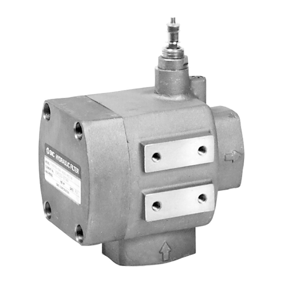
Safety Instructions Caution We develop, design, and manufacture our products to be used for automatic control equipment, and provide them for peaceful use in manufacturing industries. Use in non-manufacturing industries is not covered. Products we manufacture and sell cannot be used for the purpose of transactions or certification specified in the Measurement Act. - Page 5 Reset button ⑬ Inspection ⑫ window Inspection window ⑦⑥⑤ ④ ① ⑭ ② ⑪ ⑩ ⑨ ⑧ OUTLET ③ ①Case ⑧Hexagon Socket Flange type only ②Element ⑨Companion flange ③O-ring ⑩Packing (O-ring) ④O-ring ⑪Plug cap ⑤Cover ⑫Differential pressure indicator ⑥Hexagon Socket ⑬Differential pressure switch Head Cap Screw ⑭Relieving valve...
- Page 6 1.Before connection, ensure the direction of inlet and outlet. 2.On models with 04~12 only, inlet port sizes are different from outlet port sizes. Port size INLET OUTLET 3.Keep spaces at opposite side of outlet for maintenance work of element replacement. 4.The unit can be mounted in any position.
- Page 7 Connect to alarm Cord Connector Micro switch Figure. 2 3. Remove the rubber plug ④ and make wiring in the following procedure. 3-1. Connect the wire properly to terminals of microswitch(NO,NC) by using connector as shown figure 2. Don’t remove the microswitch from the switch box. Use the plane connector (receptacle #187) or solder for the wiring.
- Page 8 Revision history 1st edition:March 2024 Tel: + 81 3 5207 8249 Fax: +81 3 5298 5362 https://www.smcworld.com Note: Specifications are subject to change without prior notice and any obligation on the part of the manufacturer. © SMC Corporation All Rights Reserved...
Need help?
Do you have a question about the FH99 Series and is the answer not in the manual?
Questions and answers