
Related Manuals for Infineon GTM TOM PWM 1


Summary of Contents for Infineon GTM TOM PWM 1
- Page 1 GTM_TOM_PWM_1 for KIT_AURIX_TC297_TFT GTM TOM PWM generation AURIX™ TC2xx Microcontroller Training V1.0.0 Please read the Important Notice and Warnings at the end of this document...
-
Page 2: Scope Of Work
LED. The LED is driven by pin 0 of the port 13. The state of the pin is controlled by the PWM signal generated by the TOM timer of GTM. 2020-02-11 Copyright © Infineon Technologies AG 2020. All rights reserved. - Page 3 The Clock Management Unit (CMU) is responsible for clock generation of the GTM. The Fixed Clock Generation (FXU) is one of its subunits and it provides five predefined non-configurable clocks for GTM modules, including the TOM. 2020-02-11 Copyright © Infineon Technologies AG 2020. All rights reserved.
-
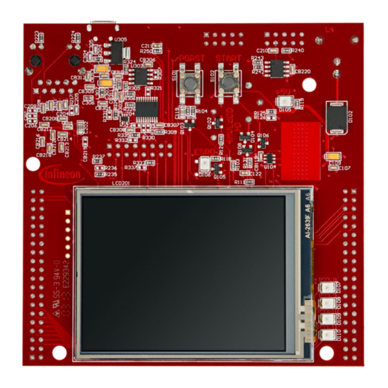
Page 4: Hardware Setup
Hardware setup This code example has been developed for the board KIT_AURIX_TC297_TFT_BC-Step. LED D107 (1) is used for this example. 2020-02-11 Copyright © Infineon Technologies AG 2020. All rights reserved. - Page 5 – Setting of the period for the PWM signal to the desired value › pin.outputPin – Selection of the LED as output pin › synchronousUpdateEnable – Enabling of synchronous update of the timer 2020-02-11 Copyright © Infineon Technologies AG 2020. All rights reserved.
- Page 6 IfxGtm_Tom_Pwm.h. Fading the LED The fading of the LED is done in the function fadeLED() by repeatedly adding or removing a step value to the duty cycle of the PWM. 2020-02-11 Copyright © Infineon Technologies AG 2020. All rights reserved.
-
Page 7: Calculation Example
������ 100 ������ In this example: ������������ = = 50000 ���������� 2 ������ CMU clock 0 Frequency of the clock PWM signal Period of PWM Duty cycle of the PWM 2020-02-11 Copyright © Infineon Technologies AG 2020. All rights reserved. - Page 8 Run and Test After code compilation and flashing the device, observe the LED D107 (1), which should be fading. 2020-02-11 Copyright © Infineon Technologies AG 2020. All rights reserved.
- Page 9 More code examples can be found on the GIT repository: › https://github.com/Infineon/AURIX_code_examples › For additional trainings, visit our webpage: › https://www.infineon.com/aurix-expert-training › For questions and support, use the AURIX™ Forum: › https://www.infineonforums.com/forums/13-Aurix-Forum 2020-02-11 Copyright © Infineon Technologies AG 2020. All rights reserved.
- Page 10 Infineon Technologies in in personal injury. customer’s applications. The data contained in this document is exclusively intended for technically trained staff.
Need help?
Do you have a question about the GTM TOM PWM 1 and is the answer not in the manual?
Questions and answers