Table of Contents
Advertisement
Advertisement
Table of Contents

Related Manuals for Elecro Engineering Titan Optima Series


Summary of Contents for Elecro Engineering Titan Optima Series
- Page 1 Titan Optima (Touchscreen) Installation & Operating Manual...
-
Page 2: Table Of Contents
Contents 1. PRODUCT OVERVIEW ......................3 2. GENERAL INSTALLATION INSTRUCTION ................ 4 2.1 Mounting instruction ......................4 2.2 Pipe work ..........................5 2.3 Flow direction ........................5 2.4 Electrical connection ......................5 2.5 Power requirements ......................6 3. OPERATING INSTRUCTIONS ..................... 7 3.1 Flow requirements ...................... -
Page 3: Product Overview
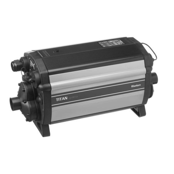
Introduction Thank you for purchasing an Optima Compact electric swimming pool heater manufactured to the highest standards in England. To ensure years of trouble-free service, please read and follow these instructions for proper installation, maintenance and use. WARNING: Failure to install the unit correctly may result in the warranty being void. Please retain this manual for future reference 1. -
Page 4: General Installation Instruction
‘L’ (mm) Power (kW) Voltage (v) 18-72 400 3 Phase 96-120 400 3 Phase 1042 18-54 220-240 3 Phase 60-90 220-240 3 Phase 1042 2. GENERAL INSTALLATION INSTRUCTION 2.1 Mounting instruction The heater should be either installed horizontally or vertically allowing enough space for the pipe connections and wiring. -
Page 5: Pipe Work
2.2 Pipe work The heater should be installed at a low point in the filtration system. It should be positioned downstream of (after) the filter and upstream of (before) any dosing or other water treatment plan. (see Fig 3.). Fig 3. 2.3 Flow direction The heater can accept flow of water from only one end (please refer to flow direction labels on the products). -
Page 6: Power Requirements
• The power supply must be fitted with a 30mA RCD. If required, the Electrician may replace the cable entry gland supplied with a larger size to secure the cable powering the heater. Minimum cable sectional area This should be calculated at 5-amp/mm for distances up to 20 metres (these sections are indicative and should be checked and adapted if necessary, for cable lengths over 20 metres). -
Page 7: Operating Instructions
3. OPERATING INSTRUCTIONS 3.1 Flow requirements The heater should be connected to a filtration system with a minimum flow volume of 12,000-litres per hour (2,640 UK gallons per hour). The maximum flow volume that the heater will operate with is 40,000- litres per hour (8,800 UK gallons per hour). -
Page 8: Digital Touchscreen Heater Overview
3.3 Digital touchscreen heater overview The Touchscreen digital heater has been pre-programmed with all the necessary parameters to ensure reliable service & operation. Below is an overview indicating the heater button keys and graphical symbols. On initial power up of the heater the digital display will be illuminated. The heating device will only be switched ‘On’... - Page 9 digital display will show ‘NORMAL’ and the graphical red coloured thermometer will ‘Animated’ whenever the heating device is switched ‘ON’. The actual pool water temperature is shown in the upper area of the display. The required temperature is shown in the lower area of the display. The required water temperature can be adjusted by touching the ‘UP / DOWN’...
- Page 10 The required Modes are selected by touching the ‘M’ button key, each touch causes the mode to change to the next mode. The display will indicate which mode is currently selected together with the clock time. (Example illustrated ‘INSTALLATION’ mode) Installation Mode When entering Installation mode, the heater and pump will immediately be turned off (if they are on) and will not be permitted to be turned on while the heater remains in any of the setup menus.
- Page 11 Touch the ‘UP’ / ‘DOWN’ button keys until the desired language is displayed then touch the ‘O.K’ button key to select. UNIT Setup After selecting ‘O.K’. For the language setup the display will then revert back to show ‘LANGUAGE’ touch the ‘UP’...
- Page 12 CLOCK Setup Touch the ‘UP’ / ‘DOWN’ button keys to display the next option which is ‘CLOCK’ touch the ‘O.K’ button key to select, the display will show ‘SET TIME’ and the current clock time, touch the ‘UP’ / ‘DOWN’ button keys to change the clock time, touch the ‘O.K’...
- Page 13 Probe Calibration Setup After selecting ‘EXIT’ for the timer setup the display will then show ‘PROBE CAL’ touch the ‘O.K’ button key to select, touch the ‘UP’ / ‘DOWN’ button keys to increase or decrease the temperature calibration adjustment, touch the ‘O.K’ button key to select, the display will then revert back to show ‘PROBE CAL’. Probe calibration is usually not required.
- Page 14 MODBUS Setup Refer to your BMS Management System manual for the required settings. SET BAUD touch the ‘O.K’ button key to select, ‘MODBUS SET BAUD’ will be displayed, touch the ‘O.K’ button key to select and ‘SET BAUD 19200 Baud’ will be displayed, touch the ‘UP’ / ‘DOWN’ button keys for the other option ‘SET BAUD 9600 Baud’...
- Page 15 Set Parity Touch the ‘O.K’ button key to select ‘MODBUS SET PARITY’ and ‘PARITY ODD’ will be displayed touch the ‘UP’ / ‘DOWN’ button keys to change ‘PARITY ODD’ to ‘PARITY EVEN’ or ‘PARITY NONE’ touch the ‘O.K’ button key to select the required setting, the display will now revert back to show ‘MODBUS SET PARITY’...
- Page 16 Normal Operating Mode Under normal conditions when the heater is connected and ‘On’ and flow has been detected by the flow switch the heater display will be as shown below indicating the following information: 1. ‘Normal’ and ‘Time’. 2. Actual water temperature. 3.
- Page 17 In this mode the heater will only heat during a timed-on period and when receiving sufficient flow. If no or insufficient flow is being received no heating will take place. When in a timed off period no heating will take place. Temperature Display Mode Select your required temperature (described earlier in this booklet).
-
Page 18: Trouble Shooting
Once the ‘Priority of Heating’ feature has been enabled the heater will take a water temperature sample every hour and the message ‘SAMPLING’ will be displayed. If the pool water temperature is below the required temperature, the heater will send a signal to the heating device to come on until the required temperature is reached. -
Page 19: Error Codes
the first reading from the second reading the number of units (kilo Watts kW) consumed can be calculated. Note that your heater is also rated in kW hours. The pool pump and heater will need to be running continuously during the test. To avoid inaccurate results when performing this test, it is important to refrain from using other high current consuming appliances in the property, such as tumble dryers, showers, cookers etc. - Page 20 Insufficient flow. - if this is the cause the display will show ‘No Flow’. Possible cause 3: If using a cartridge filter: Confirm this by running the system with the cartridge removed from your pump & filter unit, this will supply the heater with the maximum flow rate that your unit is capable of.
-
Page 21: Maintenance
5. MAINTENANCE We recommend annual maintenance and cleaning of the heater to ensure proper operation. WARNING: Before performing any maintenance on the unit isolate from the main power supply. The heater should be drained, the flow tubes and heating elements should be cleaned. Removing scale/sludge and any debris or blockages will extend life expectancy of the heating element(s) and avoid potential failures. -
Page 22: Wiring Diagrams
8. WIRING DIAGRAMS... - Page 25 Elecro Engineering Ltd Repairs Department Unit 11 Gunnels Wood Park Gunnels Wood Road Stevenage Hertfordshire SG1 2BH United Kingdom __________________________________________________________________________________ Customer Information: (ATTACH TO HEATER) ………………………………………………………………………………. Company Name: ………………………………………………………………………………. Contact Name: Daytime Telephone Number: ………………………………………………………………………………. ……………………………………………………………………………….. Email Address: ……………………………………………………………………………….. ………………………………………………………………………………..
- Page 28 11 Gunnels Wood Park, Stevenage, Herts SG1 2BH Sales@elecro.co.uk www.elecro.co.uk +44 (0) 1438 749474 © Copyright V.01 2019...
Need help?
Do you have a question about the Titan Optima Series and is the answer not in the manual?
Questions and answers