Table of Contents
Advertisement
Quick Links
Advertisement
Table of Contents

Related Manuals for Elecro Engineering Cygnet Evolution 2


Summary of Contents for Elecro Engineering Cygnet Evolution 2
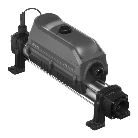
- Page 1 Cygnet Evolution 2 Pool Heater (Digital) Installation & Operating Manual...
-
Page 2: Table Of Contents
CONTENTS 1. PRODUCT OVERVIEW ......................3 2. GENERAL INSTALLATION INSTRUCTION ................ 4 2.1 Mounting instruction ......................4 2.2 Pipe work ..........................5 2.3 Flow direction ........................6 2.4 Electrical connection ......................7 2.5 Power Requirements ......................8 2.6 Dedicated RCD Safety Circuit .................... 8 3. -
Page 3: Product Overview
INTRODUCTION Thank you for purchasing a Cygnet Evolution 2 aquatic electric heater manufactured to the highest standards in England. To ensure years of trouble-free service, please read and follow these instructions for proper installation, maintenance and use. WARNING: Failure to install the unit correctly may result in the warranty being void. -
Page 4: General Installation Instruction
2. GENERAL INSTALLATION INSTRUCTION 2.1 Mounting instruction The heater should be either installed horizontally or vertically allowing enough space for the pipe connections and wiring. It should be firmly secured using screws to a firm base or wall. WARNINGS: If the heater is placed against a combustible material a fireproof barrier must be placed between the unit and the wall, this must cover a minimum of 15cm around the outside of the heater. -
Page 5: Pipe Work
2.2 Pipe work The heater should be installed at a low point in the filtration system. It should be positioned downstream of (after) the filter and upstream of (before) any dosing or other water treatment plan (see Fig 3). Fig.3 Fig.4... -
Page 6: Flow Direction
2.3 Flow direction The heater can accept flow of water from only one end (see Fig. 5). If the flow direction is opposite to Fig. 5 the heater must be rotated by 180° so the flow switch is always where the water exits. DO NOT REVERSE THE FLOW SWITCH INLET OUTLET... -
Page 7: Electrical Connection
If flexible pipework is used Connect the pipe to the non-threaded side of the hosetail and secure using two jubilee clips (See Fig. 7) • The hosetail may need to be cut depending on the diameter of the pipe. NOTE: •... -
Page 8: Power Requirements
Connections • To connect the power supply cable, remove access cover (see Fig. 8). • Make sure that all connections to the terminal block are correct as per the label inside the heater and they are tight. • Make sure not to expose the cable to anything which can cause damage to it i.e. sharp edges, hot surfaces, or crush hazards. -
Page 9: Operating Instructions
3. OPERATING INSTRUCTIONS 3.1 Flow requirements The flow rate of water into the heater must not exceed 17,000 litres per hour (17m /hour/3,740 UK gallons per hour). A higher flow rate will require the installation of a bypass to prevent damage to the heater elements. -
Page 10: Choose Your Language
Fig. 10 Fig. 11 3.4 Choose your language On initial power up, the display will illuminate and show a language message, (see Fig. 12). If the controller detects inactivity for 3 seconds, it will default the language to English. Fig. 12 There are five languages to choose from English, French, Spanish, German and Russian. -
Page 11: Set Point
3.5 Set point The setting can be changed (desired water temperature), any time by simply turning the knob clockwise or anti clockwise until the required temperature is shown on the display (see Fig.13). To confirm the changes, press the knob button (OK). The display should show ‘SAVED’... -
Page 12: Calibrate Temperature
The heater will stay on until the set temperature point is reached. When reached the heater will maintain the pool temperature within 0.5°C differential. 3.7 Calibrate temperature If for any reason the water temperature displayed by the controller is different to the water temperature in the pool, adjust this by pressing and holding the dial button for five seconds. - Page 13 ➢ Heater will not switch from standby to on (Red light): In most cases this will be the result of one of the following points not being met: Possible Cause 1: The temperature point set has been achieved. To confirm the increase of the temperature set, turn the dial to a value greater than the current water temperature.
- Page 14 Possible Cause 5: SHUTDOWN HIGH AMBIENT message (See Fig.19). The heater is fitted with intelligence sensors not only monitoring the water temperature but also the temperature within the electrical enclosure. To protect the components if the temperature inside the enclosure reaches 60°C, the controller will shut down and go to STAND BY mode.
-
Page 15: Maintenance
➢ Heater is tripping circuit breaker (MCB) after few minutes/ hours of operation: If the heater is faulty it will instantly trip the circuit breaker (MCB). The most likely causes of tripping the breaker after a period of time are: Possible Cause 1: Faulty circuit breaker. -
Page 16: Warranty
7. WARRANTY This product is guaranteed from the date of purchase against faulty workmanship and materials for: – two years within Europe – one year outside Europe • The manufacturer will replace or repair, at its discretion, any faulty units or components returned to the Company for inspection. -
Page 17: Dedicated Rcd Wiring Diagram For Correct Operation Of The Cygnet Evolution 2 Heater
8. DEDICATED RCD WIRING DIAGRAM FOR CORRECT OPERATION OF THE CYGNET EVOLUTION 2 HEATER... -
Page 18: Wiring Diagrams
WIRING DIAGRAMS:... - Page 19 Elecro Engineering Ltd Repairs Department Unit 11 Gunnels Wood Park Gunnels Wood Road Stevenage Hertfordshire SG1 2BH United Kingdom __________________________________________________________________________________ Customer Information: (ATTACH TO HEATER) ………………………………………………………………………………. Company Name: ………………………………………………………………………………. Contact Name: Daytime Telephone Number: ………………………………………………………………………………. ……………………………………………………………………………….. Email Address: ……………………………………………………………………………….. ………………………………………………………………………………..
- Page 20 11 Gunnels Wood Park, Stevenage, Herts SG1 2BH Sales@elecro.co.uk www.elecro.co.uk +44 (0) 1438 749474 © Copyright V01.2019...
Need help?
Do you have a question about the Cygnet Evolution 2 and is the answer not in the manual?
Questions and answers