
Related Manuals for Elecro Engineering In-Line + Swimming Pool Heater


Summary of Contents for Elecro Engineering In-Line + Swimming Pool Heater
-
Page 1: Installation Instructions
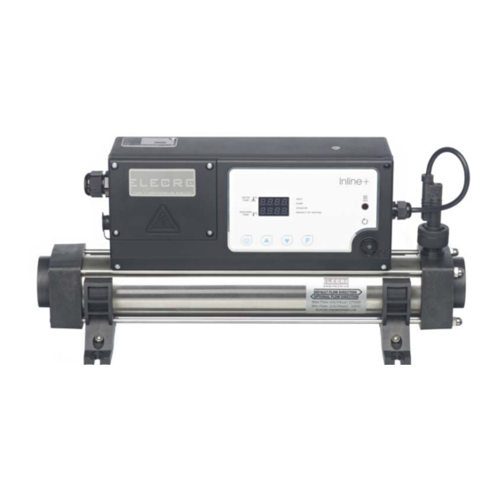
In-Line + Swimming Pool Heater Installation Instructions & Operating Manual LEASE AREFULLY EFORE NSTALLING Incorrect Installation Will Affect Your Warranty Do Not Discard, Keep For Future Reference... - Page 2 OSITIONING Your heater must be screw fixed to a firm base or wall. The heater MUST be horizontal and upright i.e. with the control enclosure located above the flow tube (see diagram below). Under no circumstances should the heater be operated in any other orientation. The heater should be installed at a low point in the filtration system.
-
Page 3: Electrical Connection
EATHER ROTECTION The heater should be installed within a dry weatherproof enclosure. CAUTION If the heater is not used during winter months it must be drained to prevent frost damage. Upon completion of the installation, run the water-circulating pump to purge the system & heater of air (i.e. -
Page 4: Water Quality
EQUIREMENTS Your heater is factory set to accept input water flow entering on the left and exiting on the right, this can be reversed by rotating the flow switch 180° (i.e. ½ turn) (see diagram below). Warning! The flow switch paddle can be damaged when reversing the flow direction if it is lifted by more than 5-mm from its housing and turned with force. - Page 5 IGITAL ONTROLLER The digital controller fitted to the In-Line + heater has been pre-programmed with all the necessary parameters to ensure reliable service & operation. Below is a key explaining the controllers buttons & LED signals however these will all be explained in detail later in this booklet.
- Page 6 NTERLOCK ABLE The In-Line + heater is supplied complete with a pump interlock cable that connects into the left hand side of the heater enclosure, directly below the power in cable entry gland. To connect simply remove the rubber protection cap from the female connector fitted to the heater enclosure, insert the male connector supplied on the 5m cable.
- Page 7 ROUBLE HOOTING Heater will not switch to HEATER ON mode In most cases this will be the result of one of the following not being met. Possible Cause 1.) The required temperature has been achieved. To confirm that the digital controller is requesting the unit to heat check that the window next to the word HEAT is illuminated.
-
Page 8: Troubleshooting Continued
ROUBLE HOOTING ONTINUED If using a cartridge filter: Confirm this by running the system with the cartridge removed from your pump & filter unit, this will supply the heater with the maximum flow rate your unit is ca- pable of. If the heater then switches on (i.e. red light on) a blocked cartridge can be confirmed to be the cause. -
Page 9: R Ohs Compliance Statement
For more information please contact your local Civic office, your household waste disposal service or the retailer where you purchased the product. HS C OMPLIANCE TATEMENT Elecro Engineering Limited certify that our Electric Swimming Pool Heater Range complies in accordance with RoHS Directive 2002/95/EC on the restriction of hazardous substances. - Page 10 CEI 801-4 CEI 801-2 CEI 801-3 of the LOW VOLTAGE directive 73/23/EEC. The harmonised standards have been applied EN 60335-2-35 Elecro Engineering Limited Unit 11 Gunnels Wood Park Stevenage Hertfordshire SG1 2BH Tel: +44 (0) 1438 749 474 Fax : +44 (0) 1438 361 329 Website: www.elecro.co.uk...
Need help?
Do you have a question about the In-Line + Swimming Pool Heater and is the answer not in the manual?
Questions and answers