Advertisement
Quick Links
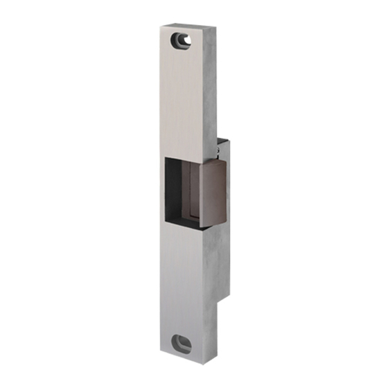
The following instructions cover all models of the 30-4 Electric Strike.
INSTALLATION:
1. For proper installation of the 30-4 Electric Strike, refer to the appropriate template
drawing. The centerline of the latch bolt must be aligned with the centerline of the strike.
NOTE: Not compatible with SDC 6000 Series Rim Devices. Check manufacturers exit
device template for compatibility.
2. Prior to installation, make the necessary wire connections per the appropriate wiring diagram.
3. Proper operating voltage must be supplied to the strike if it is to function correctly. Voltage
at the strike must be within +/-10% of the required voltage listed on the strike label.
4. To install the strike into the frame opening:
A) Position the wiring either down, up or toward the back of the hollow metal frame,
making sure that it stays completely out of the way of the strike to avoid being pinched
during installation.
B) Mount the strike using the screws supplied.
5. After installation, check the horizontal alignment. Be certain that the centerline of the latch
bolt is aligned with the centerline of the strike.
6. In case of misalignment, there is a 3/16" horizontal adjustment between the strike
mechanism and the face plate. To adjust:
A) Remove mounting screws.
B) Remove strike from frame.
C) Loosen the two (2) #12-24 x 3/8" hex washer head cap screws.
D) Reposition strike and re-tighten cap screws.
OPERATION:
The SDC 30-4 Electric Strike is a solenoid operated device.
1. NON-FAIL SAFE
When power is applied the solenoid pulls the locking cam into the unlocked position
allowing the door to be opened. If power fails the strike will remain locked.
NOTE: Non-fail safe strikes for use in fire rated doors can only be operated by momentary
contact switching (energized only when the push button is held depressed) and can not
be held in the unlocked position.
2. FAIL SAFE:
When the power is applied the solenoid pushes the locking cam into the locked position
and the door can not be opened. If power fails the strike will unlock.
OPERATION NOTE: This product may be provided fail safe or non-fail safe. Fail safe versions
P:\INSTALLATION INST\ELECTRIC STRIKES\INST-30 Series\INST-30-4.vsd
801 Avenida Acaso, Camarillo, Ca. 93012
• (805) 494-0622 • www.sdcsecurity.com
E-mail: service@sdcsecurity.com
INSTALLATION INSTRUCTIONS
30-4 ELECTRIC STRIKE
allow exit in the event of a power failure. Fail secure version do not.
Consult with the local authority having jurisdiction concerning the
installation of this type of product and whether listed panic hardware is
required to allow emergency exit from the secured area.
Rev -
12/10
Page 1
Advertisement

Subscribe to Our Youtube Channel
Related Manuals for SDC 30-4


Summary of Contents for SDC 30-4
-
Page 1: Installation Instructions
The following instructions cover all models of the 30-4 Electric Strike. INSTALLATION: 1. For proper installation of the 30-4 Electric Strike, refer to the appropriate template drawing. The centerline of the latch bolt must be aligned with the centerline of the strike. -
Page 2: Optional Features
INSTALLATION INSTRUCTIONS 30-4 ELECTRIC STRIKE OPTIONAL FEATURES; 1. LBM SWITCH (Latch Bolt Monitor) – A switch operated by the switch tripper that signals whether or not the latch bolt is extended into the strike. 2. LCM SWITCH (Locking Cam Monitor) – A switch operated by the roll pin on the locking cam that monitors the position of the locking cam and signals that the strike is either locked or unlocked. - Page 3 30-4 SERIES ELECTRIC STRIKE WIRING DIAGRAMS 30-4 Series LCBMA 30-4 Series LCBM Wiring Diagram Wiring Diagram Attachment of New Rectifier Solenoid Solenoid (Required when supplying AC power DC solenoid to a unit with a DC solenoid) Lock Cam/Bolt Monitor Switch...
- Page 4 30-4 ELECTRIC STRIKE WIRING DIAGRAMS 30-4 LBM wiring diagram 30-4 LCM wiring diagram Solenoid Solenoid Fail Safe Controls Indication Control Terminal Latch Bolt Latch Bolt Power Power Strip Monitor Switch Monitor Switch Typical Control Push Schematic for Dotted Lines Represent...
-
Page 5: Maintenance And Lubrication Instructions
MAINTENANCE AND LUBRICATION INSTRUCTIONS Under normal usage the 30-4 Electric Strike should be cleaned and lubricated once a year to maintain it’s reliability. In applications with high usage or dirty conditions more frequent service may be necessary. Lubrication points are identified in the illustration. - Page 6 15. Reassemble the strike to the face plate. Locked Position Loosen set screws to position solenoid. Tighten after position is set. Unlocked Position Front View Front View Fail Safe Non Fail Safe Shown Locked Shown Unlocked P:\INSTALLATION INST\ELECTRIC STRIKE\INST-30-4.vsd Rev - 01/11 Page 6...
Need help?
Do you have a question about the 30-4 and is the answer not in the manual?
Questions and answers