
Related Manuals for Aaeon BOXER-6404


Summary of Contents for Aaeon BOXER-6404
-
Page 1: Intel Celeron
E m b e d d e d B o x P C B O X E R - 6 4 0 4 BOXER-6404 ® ® Intel Celeron / Atom™ Processor LAN, HDMI, USB, COM BOXER-6404 Manual 1 September 8, 2015 DISTRIBUTED BY TEXIM EUROPE... -
Page 2: Copyright Notice
AAEON assumes no liabilities resulting from errors or omissions in this document, or from the use of the information contained herein. AAEON reserves the right to make changes in the product design without notice to its users. DISTRIBUTED BY TEXIM EUROPE... - Page 3 E m b e d d e d B o x P C B O X E R - 6 4 0 4 Acknowledgments • AMI is a trademark of American Megatrends Inc. • ™ CFast is a trademark of the Compact Flash Association. •...
-
Page 4: Packing List
B O X E R - 6 4 0 4 Packing List Before you begin operating your PC, please make sure that the following materials have been shipped: BOXER-6404 Embedded Box PC Power Adapter DVD-ROM for manual (in PDF format) and... - Page 5 E m b e d d e d B o x P C B O X E R - 6 4 0 4 Safety & Warranty Please read the following safety instructions carefully. It is advised that you keep this manual for future references Disconnect this device from any AC supply before cleaning.
- Page 6 E m b e d d e d B o x P C B O X E R - 6 4 0 4 13. As most electronic components are sensitive to static electrical charge, be sure to ground yourself to prevent static charge when installing the internal components.
- Page 7 E m b e d d e d B o x P C B O X E R - 6 4 0 4 This device complies with Part 15 FCC Rules. Operation is subject to the following two conditions: (1) this device may not cause harmful interference, and (2) this device must accept any interference received including interference that may cause undesired...
- Page 8 E m b e d d e d B o x P C B O X E R - 6 4 0 4 China RoHS Requirements 产品中有毒有害物质或元素名称及含量 AAEON Boxer/ Industrial System 有毒有害物质或元素 部件名称 铅 汞 镉 六价铬 多溴联苯 多溴二苯 醚(PBDE)
- Page 9 E m b e d d e d B o x P C B O X E R - 6 4 0 4 China RoHS Requirements Poisonous or Hazardous Substances or Elements in Products AAEON Embedded Box PC/ Industrial System Poisonous or Hazardous Substances or Elements Hexavalent Polybrominated...
-
Page 10: Table Of Contents
E m b e d d e d B o x P C B O X E R - 6 4 0 4 Contents Chapter 1 General Information 1.1 Introduction ..............1-2 1.2 Features ..............1-3 1.3 Specifications ............1-4 Chapter 2 Quick Installation Guide 2.1 Product Overview ............ - Page 11 E m b e d d e d B o x P C B O X E R - 6 4 0 4 2.4.12 HDMI Port 1,2 (CN20,21) ......2-17 2.4.13 LPC Port (CN22) ......... 2-18 2.4.14 SPI Programming Header (CN23) ....2-19 Chapter 3 AMI BIOS Setup 3.1 System Test and Initialization.
-
Page 12: Chapter 1 General Information
E m b e d d e d B o x P C B O X E R - 6 4 0 4 Chapter General Information Chapter 1 General Information DISTRIBUTED BY TEXIM EUROPE... -
Page 13: Introduction
BOXER-64 series, not even PICO-ITX system. With this tiny form factor, customers can fit it almost anywhere, and it provides quite a lot of I/O ports for basic applications. BOXER-6404 adopts a reliable fanless design for most rugged environment. It also provides wireless communication features for users wishing to build up a network connection at any locations. -
Page 14: Features
E m b e d d e d B o x P C B O X E R - 6 4 0 4 1.2 Features • Slim Design • 4 LAN, 2 HDMI • Supports Wide Operating Temperature Chapter 1 General Information DISTRIBUTED BY TEXIM EUROPE... -
Page 15: Specifications
E m b e d d e d B o x P C B O X E R - 6 4 0 4 1.3 Specifications ® CPU Intel Atom™ N2807/ Celeron® J1900 Chipset System Memory 204-pin DDR3L 1333 MHz SODIMM x 1, up to 8 GB, (J1900) 204-pin DDR3L 1333 MHz SODIMM x 1, up to 4 GB, (N2807) - Page 16 E m b e d d e d B o x P C B O X E R - 6 4 0 4 - Audio - KB/MS - Others Expansion - PCIe - MiniCard Half MiniCard x 1 (USB Only) -...
- Page 17 E m b e d d e d B o x P C B O X E R - 6 4 0 4 Dimension (W x H x D) 166 x 106.6 x 30 mm (6.5 x 4.2 x 1.2”) ...
-
Page 18: Chapter 2 Quick Installation Guide
E m b e d d e d B o x P C B O X E R - 6 4 0 4 Chapter Quick Installation Guide Chapter 2 Hardware Installation DISTRIBUTED BY TEXIM EUROPE... -
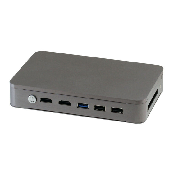
Page 19: Product Overview
E m b e d d e d B o x P C B O X E R - 6 4 0 4 2.1 Product Overview Units in mm 2 - 2 Chapter 2 Hardware Installation DISTRIBUTED BY TEXIM EUROPE... -
Page 20: Setting Jumpers
E m b e d d e d B o x P C B O X E R - 6 4 0 4 2.2 Setting Jumpers You configure your card to match the needs of your application by setting jumpers. A jumper is the simplest kind of electric switch. It consists of two metal pins and a small metal clip (often protected by a plastic cover) that slides over the pins to connect them. -
Page 21: List Of Jumpers
E m b e d d e d B o x P C B O X E R - 6 4 0 4 2.3 List of Jumpers The board has a number of jumpers that allow you to configure your system to suit your application. -
Page 22: Clear Cmos (Jp12 Pin 1,3,5)
E m b e d d e d B o x P C B O X E R - 6 4 0 4 2.3.1 Clear CMOS (JP12 pin 1, 3, 5) Normal (Default) Clear CMOS 2.3.2 Auto Power Button Enable/ Disable Selection (JP12 pin 2, 4, 6) Enable Disable (Default) - Page 23 E m b e d d e d B o x P C B O X E R - 6 4 0 4 PWRBTN# 2 - 6 Chapter 2 Hardware Installation DISTRIBUTED BY TEXIM EUROPE...
-
Page 24: List Of Connectors
E m b e d d e d B o x P C B O X E R - 6 4 0 4 2.4 List of Connectors The board has a number of connectors that provides access to external devices such as storage devices, power units, expansion ports, etc. - Page 25 E m b e d d e d B o x P C B O X E R - 6 4 0 4 CN22 LPC Expansion Connector CN23 SPI Programming Header 2 - 8 Chapter 2 Hardware Installation DISTRIBUTED BY TEXIM EUROPE...
-
Page 26: Com Port Rs-232 (Cn1)
E m b e d d e d B o x P C B O X E R - 6 4 0 4 2.4.1 COM Port RS-232 (CN1) Pin Name Signal Type Signal Level ±9V ±9V ±9V 2.4.2 +12 V Input (CN2) Pin Name Signal Type Signal Level... -
Page 27: Lan (Rj-45) Port 1,2,3,4 (Jp3,4,5,6)
E m b e d d e d B o x P C B O X E R - 6 4 0 4 2.4.3 LAN (RJ-45) Port 1,2,3,4 (JP3,4,5,6) Pin Name Signal Type Signal Level MDI0+ DIFF MDI0- DIFF MDI1+ DIFF MDI2+ DIFF... -
Page 28: Sata Port (Cn8)
E m b e d d e d B o x P C B O X E R - 6 4 0 4 2.4.5 SATA Port (CN8) Pin 1 Pin 7 Pin Name Signal Type Signal Level SATA_TXP1 DIFF SATA_TXN1 DIFF SATA_RXN1 DIFF... - Page 29 E m b e d d e d B o x P C B O X E R - 6 4 0 4 SATA_RXN0 DIFF SATA_RXP0 DIFF CFD_LED# +3.3 V +V3.3S +3.3 V +V3.3S +3.3 V 2 - 12 Chapter 2 Hardware Installation DISTRIBUTED BY TEXIM EUROPE...
-
Page 30: Minicard Slot (Cn13) (Usb Port2 Only)
E m b e d d e d B o x P C B O X E R - 6 4 0 4 2.4.8 MiniCard Slot (CN13) (USB Port2 Only) Pin Name Signal Type Signal Level WAKE_PCIE0#_3P3 +V3.3A +3.3 V +V1.5S +1.5 V DIFF... - Page 31 E m b e d d e d B o x P C B O X E R - 6 4 0 4 BUF_PLT_RST# +3.3 V DIFF +V3.3A +3.3 V DIFF +V1.5S +1.5 V SMB_CLK_3P3_FA +3.3 V DIFF SMB_DATA_3P3_FA +3.3 V DIFF USB_DN2 DIFF...
-
Page 32: Battery (Cn14)
E m b e d d e d B o x P C B O X E R - 6 4 0 4 +V1.5S +1.5 V +V3.3A +3.3 V 2.4.9 Battery (CN14) Pin Name Signal Type Signal Level +3.3 V 3.3 V 2.4.10 USB 3.0 Port 0 (CN17) Pin Name... -
Page 33: Usb 2.0 Port 1,3 (Cn18,19)
E m b e d d e d B o x P C B O X E R - 6 4 0 4 USB0_D+ DIFF USB0_SSRX− DIFF USB0_SSRX+ DIFF USB0_SSTX- DIFF USB0_SSTX+ DIFF 2.4.11 USB 2.0 Port 1, 3 (CN18,19) Standard USB Connector Pin Name Signal Type... -
Page 34: Hdmi Port 1,2 (Cn20,21)
E m b e d d e d B o x P C B O X E R - 6 4 0 4 2.4.12 HDMI Port 1, 2 (CN20,21) Pin Name Signal Type Signal Level TMDS_DAT2+ DIFF TMDS_DAT2- DIFF TMDS_DAT1+ DIFF TMDS_DAT1- DIFF... -
Page 35: Lpc Port (Cn22)
E m b e d d e d B o x P C B O X E R - 6 4 0 4 DDC_DATA +5 V +5 V HPLG_DETECT 2.4.13 LPC Port (CN22) Pin Name Signal Type Signal Level LAD0 +3.3 V LAD1 +3.3 V... -
Page 36: Spi Programming Header (Cn23)
E m b e d d e d B o x P C B O X E R - 6 4 0 4 LDRQ0 LDRQ1 SERIRQ +3.3 V 2.4.14 SPI Programming Header (CN23) Pin Name Signal Type Signal Level SPI_SO_F SPI_CLK_F +V3.3A_SPI +3.3 V... - Page 37 E m b e d d e d B o x P C B O X E R - 6 4 0 4 2.5 Installing DRAM Remove the screws as shown below Slot in the RAM diagonally into the slot, push down to secure.
- Page 38 E m b e d d e d B o x P C B O X E R - 6 4 0 4 Re-tighten the screws 2 - 21 Chapter 2 Hardware Installation DISTRIBUTED BY TEXIM EUROPE...
-
Page 39: Chapter 3 Ami Bios Setup
E m b e d d e d B o x P C B O X E R - 6 4 0 4 Chapter BIOS Setup Chapter 3 AMI BIOS Setup 3-1 DISTRIBUTED BY TEXIM EUROPE... -
Page 40: System Test And Initialization
4. The CMOS memory has lost power and the configuration information has been erased. The BOXER-6404 CMOS memory has an integral lithium battery backup for data retention. However, you will need to replace the complete unit when it finally runs out. -
Page 41: Ami Bios Setup
E m b e d d e d B o x P C B O X E R - 6 4 0 4 3.2 AMI BIOS Setup AMI BIOS ROM has a built-in Setup program that allows users to modify the basic system configuration. This type of information is stored in battery-backed CMOS RAM and BIOS NVRAM so that it retains the Setup information when the power is turned off. - Page 42 E m b e d d e d B o x P C B O X E R - 6 4 0 4 Setup Menu Setup submenu: Main Press “Delete” to enter Setup Chapter 3 AMI BIOS Setup 3-4 DISTRIBUTED BY TEXIM EUROPE...
- Page 43 E m b e d d e d B o x P C B O X E R - 6 4 0 4 Setup submenu: Advanced Chapter 3 AMI BIOS Setup 3-5 DISTRIBUTED BY TEXIM EUROPE...
- Page 44 E m b e d d e d B o x P C B O X E R - 6 4 0 4 Advanced -> ACPI Settings Options summary: ACPI Sleep Suspend Disabled State S3 (Suspend to RAM) Optimal Default, Failsafe Default Select the highest ACPI sleep state the system will enter when the SUSPEND button is pressed.
- Page 45 E m b e d d e d B o x P C B O X E R - 6 4 0 4 Power Mode ATX Type Optimal Default, Failsafe Default AT Type Select power supply mode Wake on Ring Disabled Optimal Default, Failsafe Default Enabled...
- Page 46 E m b e d d e d B o x P C B O X E R - 6 4 0 4 Enable or disable System wake on alarm event. Wake up time is current time + Increase minutes. Wake up minute increase Chapter 3 AMI BIOS Setup 3-8...
- Page 47 E m b e d d e d B o x P C B O X E R - 6 4 0 4 Advanced -> F81801 Super IO Configuration Chapter 3 AMI BIOS Setup 3-9 DISTRIBUTED BY TEXIM EUROPE...
- Page 48 E m b e d d e d B o x P C B O X E R - 6 4 0 4 Advanced -> Super IO Configuration Serial Port 1 Configuration Chapter 3 AMI BIOS Setup 3-10 DISTRIBUTED BY TEXIM EUROPE...
- Page 49 E m b e d d e d B o x P C B O X E R - 6 4 0 4 Advanced -> H/W Monitor Chapter 3 AMI BIOS Setup 3-11 DISTRIBUTED BY TEXIM EUROPE...
- Page 50 E m b e d d e d B o x P C B O X E R - 6 4 0 4 Advanced -> CPU Configuration Options summary: Intel Disabled Virtualization Enabled Optimal Default, Failsafe Default Technology When enabled, a VMM can utilize the additional hardware capabilities provided by Vander pool Technology Chapter 3 AMI BIOS Setup 3-12 DISTRIBUTED BY TEXIM EUROPE...
- Page 51 E m b e d d e d B o x P C B O X E R - 6 4 0 4 Advanced -> CPU Configuration Socket 0 CPU Information Chapter 3 AMI BIOS Setup 3-13 DISTRIBUTED BY TEXIM EUROPE...
- Page 52 E m b e d d e d B o x P C B O X E R - 6 4 0 4 Advanced -> SATA Configuration Options summary: Serial-ATA (SATA) Enabled Default Disabled En/Disable SATA SATA Speed Support Gen1 Gen2 Default SATA Speed Support Gen1 or Gen2...
- Page 53 E m b e d d e d B o x P C B O X E R - 6 4 0 4 IDE: Configure SATA controllers as legacy IDE AHCI: Configure SATA controllers to operate in AHCI mode Serial-ATA Port 0 Enabled Default Disabled...
- Page 54 E m b e d d e d B o x P C B O X E R - 6 4 0 4 Advanced -> USB Configuration Options summary: Legacy USB Support Enabled Optimal Default, Failsafe Default Disabled Auto Enables BIOS Support for Legacy USB Support. When enabled, USB can be functional in legacy environment like DOS.
- Page 55 E m b e d d e d B o x P C B O X E R - 6 4 0 4 Type) Floppy Forced FDD Hard Disk CDROM If Auto. USB devices less than 530MB will be emulated as Floppy and remaining as Floppy and remaining as hard drive.
- Page 56 E m b e d d e d B o x P C B O X E R - 6 4 0 4 Chipset Chapter 3 AMI BIOS Setup 3-18 DISTRIBUTED BY TEXIM EUROPE...
- Page 57 E m b e d d e d B o x P C B O X E R - 6 4 0 4 Chipset -> Host Bridge Options summary: Primary IGFX Boot VBIOS Default Optimal Default, Failsafe Default Display HDMI1 HDMI2 Select the Video device Chapter 3 AMI BIOS Setup 3-19...
- Page 58 E m b e d d e d B o x P C B O X E R - 6 4 0 4 Chipset -> South Bridge Chapter 3 AMI BIOS Setup 3-20 DISTRIBUTED BY TEXIM EUROPE...
- Page 59 E m b e d d e d B o x P C B O X E R - 6 4 0 4 Chipset -> South Bridge -> USB Configuration (Default Setting) Chapter 3 AMI BIOS Setup 3-21 DISTRIBUTED BY TEXIM EUROPE...
- Page 60 E m b e d d e d B o x P C B O X E R - 6 4 0 4 Security Setup submenu: Security Change User/Administrator Password You can set a User Password once an Administrator Password is set.
- Page 61 E m b e d d e d B o x P C B O X E R - 6 4 0 4 be prompted to retype your password for a final confirmation. Press Enter again after you have retyped it correctly. Removing the Password Highlight this item and type in the current password.
- Page 62 E m b e d d e d B o x P C B O X E R - 6 4 0 4 Boot Options summary: Quiet Boot Disabled Enabled Default En/Disable showing boot logo. Do not launch Default Enabled En/Disable PXE boot * Only LAN1 and LAN2 supports PXE Chapter 3 AMI BIOS Setup 3-24...
- Page 63 E m b e d d e d B o x P C B O X E R - 6 4 0 4 Save & Exit Chapter 3 AMI BIOS Setup 3-25 DISTRIBUTED BY TEXIM EUROPE...
-
Page 64: Chapter 4 Driver Installation
E m b e d d e d B o x P C B O X E R - 6 4 0 4 Chapter D river Installation 4 -1 Chapter 4 Driver Installation DISTRIBUTED BY TEXIM EUROPE... - Page 65 E m b e d d e d B o x P C B O X E R - 6 4 0 4 The BOXER-6404 comes with a DVD-ROM that contains all the drivers and utilities you need to setup your product.
- Page 66 E m b e d d e d B o x P C B O X E R - 6 4 0 4 4.1 Installation Insert the driver disk into the disk drive. And install the drivers from Step 1 to Step 6 in order. Step 1 –...
- Page 67 E m b e d d e d B o x P C B O X E R - 6 4 0 4 Step 4 – Install TXE Driver (Windows 8.1 only) 1. Open the Step4 - TXE folder and open the SetupTXE.exe file 2.
-
Page 68: Appendix A Programming The Watchdog Timer
E m b e d d e d B o x P C B O X E R - 6 4 0 4 Appendix Programming the Watchdog Timer Appendix A Programming the Watchdog Timer DISTRIBUTED BY TEXIM EUROPE... -
Page 69: Watchdog Timer Registers
E m b e d d e d B o x P C B O X E R - 6 4 0 4 A.1 Watchdog Timer Registers Table 1 : Watch dog relative IO address Default Value Note I/O Base I/O Base address for Watchdog operation. -
Page 70: Watchdog Sample Program
E m b e d d e d B o x P C B O X E R - 6 4 0 4 A.2 WatchDog Sample Program ****************************************************************************** // WDT I/O operation relative definition (Please reference to Table 1) #define WDTAddr 0xA00 // WDT I/O base address Void WDTWriteByte(byte Register, byte Value);... - Page 71 E m b e d d e d B o x P C B O X E R - 6 4 0 4 ******************************************************************************* ******************************************************************************* // Procedure : AaeonWDTEnable VOID AaeonWDTEnable (){ WDTEnableDisable(1); // Procedure : AaeonWDTConfig VOID AaeonWDTConfig (byte Counter, BOOLEAN Unit){ // Disable WDT counting WDTEnableDisable(0);...
- Page 72 E m b e d d e d B o x P C B O X E R - 6 4 0 4 // Watchdog WDTRST# Enable WDTSetBit(DevReg, WDTRstBit, WDTRstVal); VOID WDTClearTimeoutStatus(){ WDTSetBit(TimerReg, StatusBit, 1); ******************************************************************************* ******************************************************************************* VOID WDTWriteByte(byte Register, byte Value){ IOWriteByte(WDTAddr+Register, Value);...
-
Page 73: Appendix B I/O Information
E m b e d d e d B o x P C B O X E R - 6 4 0 4 Appendix I/O Information Appendix B I/O Information DISTRIBUTED BY TEXIM EUROPE... -
Page 74: I/O Address Map
E m b e d d e d B o x P C B O X E R - 6 4 0 4 B.1 I/O Address Map Appendix B I/O Information DISTRIBUTED BY TEXIM EUROPE... - Page 75 E m b e d d e d B o x P C B O X E R - 6 4 0 4 Appendix B I/O Information DISTRIBUTED BY TEXIM EUROPE...
-
Page 76: Memory Address Map
E m b e d d e d B o x P C B O X E R - 6 4 0 4 B.2 Memory Address Map Appendix B I/O Information DISTRIBUTED BY TEXIM EUROPE... -
Page 77: Irq Mapping Chart
E m b e d d e d B o x P C B O X E R - 6 4 0 4 B.3 IRQ Mapping Chart Appendix B I/O Information DISTRIBUTED BY TEXIM EUROPE... - Page 78 E m b e d d e d B o x P C B O X E R - 6 4 0 4 Appendix B I/O Information DISTRIBUTED BY TEXIM EUROPE...
- Page 79 E m b e d d e d B o x P C B O X E R - 6 4 0 4 Appendix B I/O Information DISTRIBUTED BY TEXIM EUROPE...
- Page 80 E m b e d d e d B o x P C B O X E R - 6 4 0 4 Appendix B I/O Information DISTRIBUTED BY TEXIM EUROPE...
- Page 81 E m b e d d e d B o x P C B O X E R - 6 4 0 4 Appendix B I/O Information DISTRIBUTED BY TEXIM EUROPE...
- Page 82 E m b e d d e d B o x P C B O X E R - 6 4 0 4 B-10 Appendix B I/O Information DISTRIBUTED BY TEXIM EUROPE...
- Page 83 E m b e d d e d B o x P C B O X E R - 6 4 0 4 B-11 Appendix B I/O Information DISTRIBUTED BY TEXIM EUROPE...
- Page 84 E m b e d d e d B o x P C B O X E R - 6 4 0 4 B-12 Appendix B I/O Information DISTRIBUTED BY TEXIM EUROPE...
- Page 85 E m b e d d e d B o x P C B O X E R - 6 4 0 4 B-13 Appendix B I/O Information DISTRIBUTED BY TEXIM EUROPE...
- Page 86 E m b e d d e d B o x P C B O X E R - 6 4 0 4 B-14 Appendix B I/O Information DISTRIBUTED BY TEXIM EUROPE...
- Page 87 E m b e d d e d B o x P C B O X E R - 6 4 0 4 B-15 Appendix B I/O Information DISTRIBUTED BY TEXIM EUROPE...
-
Page 88: Appendix C Electrical Specifications For I/O Ports
E m b e d d e d B o x P C B O X E R - 6 4 0 4 Appendix Electrical Specifications for I/O Ports Appendix C Electrical Specifications for I/O Ports DISTRIBUTED BY TEXIM EUROPE... -
Page 89: Electrical Specifications For I/O Ports
E m b e d d e d B o x P C B O X E R - 6 4 0 4 C.1 Electrical Specifications for I/O Ports Reference Signal Name Rate output +5 V/ 1 A or COM Port +5 V/ +12 V +12 V/ 1 A +5 V Output for SATA HDD... - Page 90 Contact details The Netherlands Belgium UK & Ireland Elektrostraat 17 Zuiderlaan 14 bus 10 St. Mary’s House, Church Lane NL-7483 PG Haaksbergen B-1731 Zellik Carlton Le Moorland Lincoln LN5 9HS +31 (0)53 573 33 33 +32 (0)2 462 01 00 +44 (0)1522 789 555 F: +31 (0)53 573 33 30 +32 (0)2 462 01 25...
Need help?
Do you have a question about the BOXER-6404 and is the answer not in the manual?
Questions and answers