Chapters
Table of Contents

Related Manuals for Aaeon BOXER-6914


Summary of Contents for Aaeon BOXER-6914
- Page 1 E m b e d d e d B o x P C B O X E R - 6 9 1 4 BOXER-6914 Fanless Embedded Box PC ® Intel Atom™ D2550 1.86GHz Processor CFast™/SIM Slot 2 DIO, 14/16 COMs 2 USB 3.0, 4 USB 2.0 BOXER-6914 Manual 1 April 10, 2015...
-
Page 2: Copyright Notice
AAEON assumes no liabilities resulting from errors or omissions in this document, or from the use of the information contained herein. AAEON reserves the right to make changes in the product design without notice to its users. - Page 3 E m b e d d e d B o x P C B O X E R - 6 9 1 4 Acknowledgments • AMI is a trademark of American Megatrends Inc. • ™ CFast is a trademark of the Compact Flash Association. •...
-
Page 4: Packing List
B O X E R - 6 9 1 4 Packing List Before you begin operating your PC, please make sure that the following materials have been shipped: BOXER-6914 Embedded Box PC Phoenix Power Connector M3 x 4mm Screws ... - Page 5 E m b e d d e d B o x P C B O X E R - 6 9 1 4 Safety & Warranty Please read the following safety instructions carefully. It is advised that you keep this manual for future references Disconnect this device from any AC supply before cleaning.
- Page 6 E m b e d d e d B o x P C B O X E R - 6 9 1 4 13. As most electronic components are sensitive to static electrical charge, be sure to ground yourself to prevent static charge when installing the internal components.
- Page 7 E m b e d d e d B o x P C B O X E R - 6 9 1 4 This device complies with Part 15 FCC Rules. Operation is subject to the following two conditions: (1) this device may not cause harmful interference, and (2) this device must accept any interference received including interference that may cause undesired...
- Page 8 E m b e d d e d B o x P C B O X E R - 6 9 1 4 China RoHS Requirements 产品中有毒有害物质或元素名称及含量 AAEON Boxer/ Industrial System 有毒有害物质或元素 部件名称 铅 汞 镉 六价铬 多溴联苯 多溴二苯 醚(PBDE)
-
Page 9: Table Of Contents
E m b e d d e d B o x P C B O X E R - 6 9 1 4 Contents Chapter 1 General Information 1.1 Introduction ..............1-2 1.2 Features ..............1-3 1.3 Specifications ............1-4 1.4 Product Overview ............ - Page 10 E m b e d d e d B o x P C B O X E R - 6 9 1 4 Appendix B I/O Information B.1 I/O Address Map ..........B-2 B.2 Memory Address Map .......... B-5 B.3 IRQ Mapping Chart ..........B-6 B.4 DMA Channel Assignments .......
-
Page 11: Chapter 1 General Information
E m b e d d e d B o x P C B O X E R - 6 9 1 4 Chapter General Information Chapter 1 General Information... -
Page 12: Introduction
B O X E R - 6 9 1 4 1.1 Introduction Due to the growing popularity from the IPC market, AAEON proudly introduces the newest entry in Boxer series, BOXER-6914. Being a control center, the BOXER-6914 is suitable for Machine Control, Data Processing, Fleet Management, Data Management. -
Page 13: Features
E m b e d d e d B o x P C B O X E R - 6 9 1 4 1.2 Features Fanless Design ® Intel Atom™ D2550 Processor ® Intel NM10 Chipset Gigabit Ethernet, RJ-45 x 2 ... -
Page 14: Specifications
E m b e d d e d B o x P C B O X E R - 6 9 1 4 1.3 Specifications ® CPU Intel Atom™ D2550 Processor, 1.86 GHz ® Chipset Intel NM10 System Memory DDR3 800/1066 SODIMM x 1, Max. - Page 15 E m b e d d e d B o x P C B O X E R - 6 9 1 4 Rear I/O USB Host USB 3.0 x 2, USB 2.0 x 2 RJ-45 x 2 for Gigabit Ethernet Serial Port DB-9 x 2 for RS-232/422/485 (cableless)
- Page 16 E m b e d d e d B o x P C B O X E R - 6 9 1 4 w/ airflow, with wide-temp CFast & F ~ 131 F (-20 C ~ 55 C). Ambient w/ airflow, with wide-temp HDD & RAM F ~ 131 F (-20 C ~ 55...
-
Page 17: Product Overview
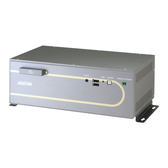
E m b e d d e d B o x P C B O X E R - 6 9 1 4 1.4 Product Overview 3 1 6 , 8 1 1 , 9 AUDIO OUT POWER REMOTE POWER 3 0 0 3 3 2 , 8 Chapter 1 General Information... - Page 18 E m b e d d e d B o x P C B O X E R - 6 9 1 4 BOXER- 6 9 1 4 UNITS: m m 1 1 , 9 DC-IN 9~30V REMOTE POWER USB/LAN COM16 COM15 F.G .
-
Page 19: Chapter 2 Quick Installation Guide
E m b e d d e d B o x P C B O X E R - 6 9 1 4 Chapter Quick Installation Guide Chapter 2 Hardware Installation... -
Page 20: List Of Jumpers
E m b e d d e d B o x P C B O X E R - 6 9 1 4 2.1 List of Jumpers The board has a number of jumpers that allow you to configure your system to suit your application. -
Page 21: List Of Carrier Board Connectors
E m b e d d e d B o x P C B O X E R - 6 9 1 4 2.2 List of Carrier Board Connectors The carrier board has a number of connectors that allow you to configure your system to suit your application. - Page 22 E m b e d d e d B o x P C B O X E R - 6 9 1 4 CN26 Remote Power SW CN27, CN28 COM Express Type 6 Connector CN29 COM 15 Connector CN30 COM 16 Connector CN31 CFast Connector DVI + VGA...
-
Page 23: List Of I/O Board Connectors
E m b e d d e d B o x P C B O X E R - 6 9 1 4 2.3 List of I/O Board Connectors The I/O board has a number of connectors that allow you to configure your system to suit your application. -
Page 24: Setting Jumpers
E m b e d d e d B o x P C B O X E R - 6 9 1 4 2.4 Setting Jumpers You configure your card to match the needs of your application by setting jumpers. A jumper is the simplest kind of electric switch. It consists of two metal pins and a small metal clip (often protected by a plastic cover) that slides over the pins to connect them. -
Page 25: Rs-232/422 Selector For Com1 And Com2 (Jp1, Jp2)
E m b e d d e d B o x P C B O X E R - 6 9 1 4 2.5 RS-232/422 Selector for COM1 and COM2 (JP1, JP2) JP1,JP2 Connection RS-232 1-2 close, 3-4 open RS-422 1-2, 3-4 close RS-232 Signal... -
Page 26: Clear Cmos (Jp10)
E m b e d d e d B o x P C B O X E R - 6 9 1 4 2.6 Clear CMOS (JP10) JP10 Function Normal (Default) Clear CMOS 2.7 Digital I/O (CN5 – Carrier Board) CN5A (Carrier board) Signal Signal... -
Page 27: Sata Power Connector (Cn24)
E m b e d d e d B o x P C B O X E R - 6 9 1 4 2.8 SATA Power Connector (CN24) Function +12V 2.9 COM 3 - 16 (CN3, 3A, 3B, 4, 4A, 4B, 5A, 5B, 6A, 6B, 29, 30) RS-232 Signal Signal... -
Page 28: Chapter 3 Ami Bios Setup
E m b e d d e d B o x P C B O X E R - 6 9 1 4 Chapter BIOS Setup Chapter 3 AMI BIOS Setup 3-1... -
Page 29: System Test And Initialization
4. The CMOS memory has lost power and the configuration information has been erased. The BOXER-6914 CMOS memory has an integral lithium battery backup for data retention. However, you will need to replace the complete unit when it finally runs down. -
Page 30: Ami Bios Setup
E m b e d d e d B o x P C B O X E R - 6 9 1 4 3.2 AMI BIOS Setup AMI BIOS ROM has a built-in Setup program that allows users to modify the basic system configuration. This type of information is stored in battery-backed CMOS RAM and BIOS NVRAM so that it retains the Setup information when the power is turned off. -
Page 31: Setup Menu
E m b e d d e d B o x P C B O X E R - 6 9 1 4 Setup Menu Setup submenu: Main Chapter 3 AMI BIOS Setup 3-4... - Page 32 E m b e d d e d B o x P C B O X E R - 6 9 1 4 Setup submenu: Advanced Chapter 3 AMI BIOS Setup 3-5...
-
Page 33: Cpu Configuration
E m b e d d e d B o x P C B O X E R - 6 9 1 4 CPU Configuration Options summary: Hyper-Threading Disabled Enabled Optimal Default, Failsafe Default Chapter 3 AMI BIOS Setup 3-6... - Page 34 E m b e d d e d B o x P C B O X E R - 6 9 1 4 IDE Configuration (IDE) Options summary: Enable Optimal Default, Failsafe Default SATA Controllers Disable En/Disable SATA Controller Optimal Default, Failsafe Default SATA Mode AHCI Chapter 3 AMI BIOS Setup 3-7...
-
Page 35: Usb Configuration
E m b e d d e d B o x P C B O X E R - 6 9 1 4 USB Configuration Options summary: Legacy USB Support Enable Optimal Default, Failsafe Default Disable Chapter 3 AMI BIOS Setup 3-8... -
Page 36: Hardware Monitor
E m b e d d e d B o x P C B O X E R - 6 9 1 4 Hardware Monitor Chapter 3 AMI BIOS Setup 3-9... - Page 37 E m b e d d e d B o x P C B O X E R - 6 9 1 4 Dynamic Digital IO Configuration Chapter 3 AMI BIOS Setup 3-10...
- Page 38 E m b e d d e d B o x P C B O X E R - 6 9 1 4 Chapter 3 AMI BIOS Setup 3-11...
- Page 39 E m b e d d e d B o x P C B O X E R - 6 9 1 4 Options summary: GPIO[35:0] Direction Input Output Optimal Default, Failsafe Default Set GPI[35:0] as Input or Output GPO[35:0] Output Level Optimal Default, Failsafe Default Chapter 3 AMI BIOS Setup 3-12...
-
Page 40: Power Management
E m b e d d e d B o x P C B O X E R - 6 9 1 4 Power Management Options summary: ATX Type Optimal Default, Failsafe Default Power Mode AT Type Select power supply mode. Last State Optimal Default, Failsafe Default Restore on Power Loss... - Page 41 E m b e d d e d B o x P C B O X E R - 6 9 1 4 PCI Express Port Configuration Options summary: Use This Device Disabled Enabled Optimal Default, Failsafe Default Auto En/Disable/Auto PCI Express Port PCI Express Port 0 Disable Optimal Default, Failsafe Default Enable...
- Page 42 E m b e d d e d B o x P C B O X E R - 6 9 1 4 Setup submenu: Chipset Chapter 3 AMI BIOS Setup 3-15...
-
Page 43: Host Bridge
E m b e d d e d B o x P C B O X E R - 6 9 1 4 Host Bridge Chapter 3 AMI BIOS Setup 3-16... -
Page 44: South Bridge
E m b e d d e d B o x P C B O X E R - 6 9 1 4 South Bridge Chapter 3 AMI BIOS Setup 3-17... - Page 45 E m b e d d e d B o x P C B O X E R - 6 9 1 4 Security Change User/Supervisor Password You can install a Supervisor password, and if you install a supervisor password, you can then install a user password. A user password does not provide access to many of the features in the Setup utility.
- Page 46 E m b e d d e d B o x P C B O X E R - 6 9 1 4 Setup submenu: Boot Options summary: Quiet Boot Disabled Enabled Default En/Disable showing boot logo. Option ROM Messages Force BIOS Default Keep Current...
- Page 47 E m b e d d e d B o x P C B O X E R - 6 9 1 4 Setup submenu: Exit Chapter 3 AMI BIOS Setup 3-20...
-
Page 48: Chapter 4 Driver Installation
E m b e d d e d B o x P C B O X E R - 6 9 1 4 Chapter Driver Installation 4 -1 Chapter 4 Driver Installation... - Page 49 E m b e d d e d B o x P C B O X E R - 6 9 1 4 The BOXER-6914 comes with a driver disk that contains all drivers and utilities that can help you setup your product.
- Page 50 E m b e d d e d B o x P C B O X E R - 6 9 1 4 4.1 Installation: Insert the BOXER-6914 driver disk into the disk drive. And install the drivers from Step 1 to Step 8 in order. Step 1 – Install Chipset Driver 1.
- Page 51 E m b e d d e d B o x P C B O X E R - 6 9 1 4 Step 3 – Install LAN Driver 1. Open the Step 3 - LAN folder and select your OS 2.
- Page 52 E m b e d d e d B o x P C B O X E R - 6 9 1 4 Step 7 – Install F81216 Patch 1. Open the Step 7 – F81216 Patch folder and open the setup.exe file 2.
-
Page 53: Appendix A Programming The Watchdog Timer
E m b e d d e d B o x P C B O X E R - 6 9 1 4 Appendix Programming the Watchdog Timer Appendix A Programming the Watchdog Timer... -
Page 54: Watchdog Timer Initial Program
E m b e d d e d B o x P C B O X E R - 6 9 1 4 A.1 Watchdog Timer Initial Program ND_PROCESS MACRO mov ah, 4ch int 21h ENDM ;******************* Code Segment ****************** .MODEL SMALL .CODE begin:... - Page 55 E m b e d d e d B o x P C B O X E R - 6 9 1 4 out dx, al ; Set BRAM_Ctrl_Sts as 0x10 (Read & Start) dec dx mov al, 12h out dx, al inc dx mov al, 30h out dx, al...
-
Page 56: Appendix B I/O Information
E m b e d d e d B o x P C B O X E R - 6 9 1 4 Appendix I/O Information Appendix B I/O Information... -
Page 57: I/O Address Map
E m b e d d e d B o x P C B O X E R - 6 9 1 4 B.1 I/O Address Map Appendix B I/O Information... - Page 58 E m b e d d e d B o x P C B O X E R - 6 9 1 4 Appendix B I/O Information...
- Page 59 E m b e d d e d B o x P C B O X E R - 6 9 1 4 Appendix B I/O Information...
-
Page 60: Memory Address Map
E m b e d d e d B o x P C B O X E R - 6 9 1 4 B.2 Memory Address Map Appendix B I/O Information... -
Page 61: Irq Mapping Chart
E m b e d d e d B o x P C B O X E R - 6 9 1 4 B.3 IRQ Mapping Chart Appendix B I/O Information... - Page 62 E m b e d d e d B o x P C B O X E R - 6 9 1 4 Appendix B I/O Information...
- Page 63 E m b e d d e d B o x P C B O X E R - 6 9 1 4 Appendix B I/O Information...
- Page 64 E m b e d d e d B o x P C B O X E R - 6 9 1 4 Appendix B I/O Information...
-
Page 65: Dma Channel Assignments
E m b e d d e d B o x P C B O X E R - 6 9 1 4 B.4 DMA Channel Assignments B-10 Appendix B I/O Information... -
Page 66: Appendix C Programming The Digital I/O
E m b e d d e d B o x P C B O X E R - 6 9 1 4 Appendix Programming the Digital I/O Appendix C Programming the Digital I/O... -
Page 67: Dio Programming
E m b e d d e d B o x P C B O X E R - 6 9 1 4 C.1 DIO Programming 1. General Description F75113 is a low power general purpose IO chip providing 40 GPIO. Level or pulse mode can be programmed by registers so all GPIO can be programmed to logic one, zero, high pulse or low pulse. - Page 68 E m b e d d e d B o x P C B O X E R - 6 9 1 4 only supported 39 GPIO function and the pin 4 won’t be used for GPIO function. If user wants to access internal register by SMBus interface, the pin 48, 1, 2, 3 must be set internal pull-high with 10KΩ.
- Page 69 E m b e d d e d B o x P C B O X E R - 6 9 1 4 and their default value. Please refer each device chapter if you want more detail information. Appendix C Programming the Digital I/O...
- Page 70 E m b e d d e d B o x P C B O X E R - 6 9 1 4 4. GPIO Function The F75113 with GPIO0X~GPIO4X General Purpose I/O port is composed of independent I/O pins controlled and controls multi-pin function by Index 02~06h register.
- Page 71 E m b e d d e d B o x P C B O X E R - 6 9 1 4 Appendix C Programming the Digital I/O...
- Page 72 E m b e d d e d B o x P C B O X E R - 6 9 1 4 5. Hi-Safe setting DIO Appendix C Programming the Digital I/Os...
- Page 73 E m b e d d e d B o x P C B O X E R - 6 9 1 4 Appendix C Programming the Digital I/O...
- Page 74 E m b e d d e d B o x P C B O X E R - 6 9 1 4 Appendix C Programming the Digital I/Os...
- Page 75 E m b e d d e d B o x P C B O X E R - 6 9 1 4 C-10 Appendix C Programming the Digital I/O...
- Page 76 BOXER-6914 嵌入式无风扇型工业控制计算机 USER’S MANUAL(中文版 ) Version 1.0 - 1 -...
- Page 77 版权声明 本文件已经申请版权……,原生产商拥有对本产品进行随时变更而不必通知的权利。 未经允许,不得以任何形式或用任何手段对本手册进行复制,拷贝,翻译或者传播。本手册 中的内容是准确可靠的, 但是, 原生产商对由于其使用而带来的结果或者因使用而带来的任 何损害第三方权益的结果不承担任何责任。 本文件中的内容只包含产品信息, 并且可以在未通知的情况下进行变更。 在制作本文件的过 程中,我们努力确保其准确性,但是研扬不承担由本文件内容的错误或者疏漏,或者由使用 此处包含的信息而带来的任何责任。 研扬(AAEON)保留在产品设计中进行更改而不通知其用户的权利。 包装清单 在您打开包装后,请检查包装内如下对象是否齐全: BOXER-6914 整机一台 电源连接器一个 硬盘螺丝四颗 壁挂架螺丝四颗 壁挂架一组 驱动光盘光盘一片(内含使用手册) 保修证明以及合格证一套 如果以上任何物品不齐全或者有损坏,请立刻与当地经销商或者销售代表联系。 - 2 -...
- Page 78 安全与警告 1. 请仔细阅读如下安全说明。 2. 请保存好本用户手册以供日后参考。 3. 在清洁本设备之前, 首先要切断所有交流电源。 不要用液体或者气雾清洁剂进行清 洗。请使用潮湿的棉布进行清洁。 4. 电源插座必须安装在设备附近,以方便接通电源。 5. 保持设备干燥,以防潮湿 6. 安装过程中,须将本设备放置在牢固的桌面。如果跌落会造成损坏。 7. 在接入电源之前请确认设备与电源电压等是否匹配。 8. 请将电源线绑好,以防止被踩到。不要在电源线上放置任何物体。 9. 请认真阅读设备上的任何小心和警告提示内容 10.如果长时间不使用本设备,请断开电源线以防瞬间高压带来损伤。 11.请不要在机器上倾倒任何液体,因为可能导致火灾或者电源短路。 12.请不要打开本设备,出于安全的原因,只有有资格的维修人员才能打开本设备。 13.如有以下情况发生,请专业维修人员检查本设备: a) 电源线或者插头损坏 b) 有液体渗入设备内部 c) 设备已经暴露在潮湿的环境中 d) 设备不能正常工作,或者不能使其按照使用说明书使其运转 e) 设备跌落或者损伤 f) 设备有任何明显的损坏的迹象 14.不要将设备储存在温度低于-20℃(-4°F)或者高于+80℃(158°F)的环境中,以免 造成损坏。 FCC 安全警告...
- Page 79 目 录 第一章 规格介绍…………… …………………………………………………… P5 1.1 无风扇型号工控机介绍…………………………………………………… P5 1.2 可供选择的型号介绍……………………………………………………… P7 1.3 可供选配的配件介绍……………………………………………………… P8 第二章 安装及使用注意事项 …………………………………………………… P9 2.1 装箱单的核查……………………………………………………………… P9 2.2 软件的安装………………………………………………………………… P9 2.3 前后面板接口介绍………………………………………………………… P10 2.4 硬盘模组的安装…………………………………………………………… P12 2.5 内容模组的安装…………………………………………………………… P13 第三章 搬运的注意事项 ………………………………………………………… P13 - 4 -...
-
Page 80: 第一章 规格介绍
第一章 规格介绍 1.1 BOXER-6914 无风扇型号工控机介绍 欢迎您购买研扬 系列无风扇型号工控机产品! BOXER-6914 BOXER-6914 嵌入式控制器在目前市场上同类产品中,性能最佳的多功能模块中的一款。 BOXER-6914 军工级紧凑型工业控制终端,主要技术指标包括:抗震动能力可达 5G/5~500Hz (w/CFD);抗冲击能力可达 50G (w/CFD);主要应用于自动售票机、闸机、工厂自动化等多个领 域。 技术特色: 基于 Intel® Atom™ D2550 1.86 GHz 处理器的无风扇设计 單邊出線 专为节省空间而设计的 专为节省空间而设计的壁挂式安装 支持嵌入式操作系统的应用 支持 CF 卡和可选得 HDD 模块 ... - Page 81 详细规格: Intel® Atom™ D2550 1.86GHz 低功耗处理器 系统内存 204-pin DDR3 SO-DIMM x 2,最大 4GB(PC 800/1066 MHz) DB-15 x 1 VGA 连接器 显示端口 DVI-D 连接器 以太网 10/100/1000 Base-TX RJ-45 连接器 x 2 2.5” HDD/SSD bay x 1 磁盘驱动器 CFast™ 插槽 x 1 RS-232/422/485 x 2 串口...
-
Page 82: 可供选择的型号介绍
注意 1.此为 A 级产品,在生活环境中,该产品可能会造成无线电干扰。 2.用错误型号电池更换会有爆炸危险,务必按照说明处置用完的电池 若更换电池有问题,请恰研扬中国各地分公司询问 尺寸规格 1.2 可供选择的型号介绍 BOXER-6914 系列详细型号列举如下,用户可以根据自己的实际需求进行选择: 嵌入式控制 PC,Intel® Atom™ D2550 CPU,9-30VDC,6USB, BOXER-6914-A00-1010 2LAN,14COM,1VGA,1DVI,Digital I/O 嵌入式控制 PC,Intel® Atom™ D2550 CPU,9-30VDC,6USB, BOXER-6914-A01-1010 2LAN,16COM,1VGA,1DVI,Digital I/O,PCIe[x1] x1,PCI x 1 嵌入式控制 PC,Intel® Atom™ D2550 CPU,9-30VDC,6USB, BOXER-6914-A02-1010 2LAN,16COM,1VGA,1DVI,Digital I/O,PCI x 2... -
Page 83: 可供选配的配件介绍
1.3 可供选配的配件介绍 附件选项 1757908401 84W 电源适配器 9761215303 模块與天線 WiFi 1702031802 电源线(美规) 1702031803 电源线(欧规) 170203180E 电源线(日规) - 8 -... -
Page 84: 第二章 安装及使用注意事项
第二章 安装及使用注意事项 2.1 装箱单的核查 首先在使用前请您核对整机的实际配置是否与〞研扬工控机〞的装箱单一致、随机 资料是否齐全,如有异议请您与销售商联系 。 主机的标准配置一般包括: 1、 主机(相关部件)及电源线 2、 随机资料和驱动盘 3、 其它可选件(显示器等) 4、 机箱附件盒 检查完毕后,将主机与显示器或其它外设联接好后,接好电源;加电、打开工控机 电源开关,核查工控机运行情况。 注意: ★ ‧ 请不要丢掉产品原包装箱,此包装箱具有防震功能。在需要移动、运输或贮存时请 使用本机的原始包装箱另返回的部件包装如不合要求将不予保修。 ‧ 装箱单本身有保修单的功能,如另附保修单(质保书)请您在详细填写并将回执寄 回研扬科技(中国)有限公司,如未附保修单(质保书)请在维修时携带装箱单以备 说明。 ‧ 请您认真阅读随机文件并妥善保管 (请勿打开随机所带软盘的写保护, 以避免感染 病毒) 2.2 软件的安装 〞研扬〞工控机可支持大多数操作系统和应用软件,如 Windows® 7, Windows® XP,你 可任意安装而不会产生任何兼容性问题。 - 9 -... -
Page 85: 前后面板接口介绍
2.3 前后面板接口介绍 - 10 -... -
Page 86: 硬盘模组的安装
2.4 硬盘模组的安装 系统的安装只需一把螺丝刀,在安装前应准备好所有需要安装的零部件并把它们集中 到一起。 警告 :在安装 CPU 卡前机箱不能与任何电源连接,不只是将电源关掉,应将电源插头 从电源插座上拔下。如果不清楚如何安装,应请富有经验的人来指导 2.4.1 硬盘的组装 1. 将 2.5”硬盘放上硬盘固定架 2. 将硬盘和固定架叠在一起,并使用十字起子锁上螺丝将他们固定 3. 将硬盘模块固定在底盖上。 - 11 -... - Page 87 4. 将排线的另一头接到 2.5” 硬盘的 pin 脚上 5. 采用如图方式将底盖与主机联合在一起并锁上螺丝 - 12 -...
-
Page 88: 内容模组的安装
2.5 内容模组的安装 1. 将 Thermal Pad 贴上 M/B 2. 插上内存模块 章 搬运的注意事项 第三 〞研扬工控机〞的机箱及主机的外包装箱均采用特殊的设计, 具有防震功能, 能够承受 运输过程中正常的碰撞。 产品在长途运输过程中不得装在敞开的船舱或车厢中, 中途转运时不得存放在露天仓库 - 13 -... - Page 89 中,在运输过程中不允许和易燃,易爆等物品共同装运,不允许被雨、雪或其它液体物质淋 湿,不允许有机械损伤。贮存环境(-20 至+40℃,相对湿度 30%~85%) , 如用户在使用过程中需要搬运主机, 首先请妥善保护好所有仪器设备, 在完成以下步骤 后进行搬运动作。 ‧ 保存好所使用的文件 ‧ 从软盘驱动器中取出所有的软盘并妥善保管。 ‧ 关闭工控主机电源并将电源插头从电源插座上拔下。 ‧ 将主机与外设分开, 拆下显示器电缆, 拔下键盘电缆等安装在主机箱上的其它外部 设备。 ‧ 将工控主机重新包装于原始的包装箱中后即可搬运仪器设备。 - 14 -...
Need help?
Do you have a question about the BOXER-6914 and is the answer not in the manual?
Questions and answers