
Related Manuals for Aaeon BOXER-8253AI


Summary of Contents for Aaeon BOXER-8253AI
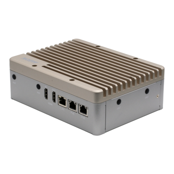
- Page 1 BOXER-8253AI Compact Fanless Embedded AI@Edge Box PC with NVIDIA® Jetson Xavier™ NX User’s Manual 2 Last Updated: February 2, 2021...
- Page 2 AAEON assumes no liabilities resulting from errors or omissions in this document, or from the use of the information contained herein. AAEON reserves the right to make changes in the product design without notice to its users.
- Page 3 Acknowledgements All other products’ name or trademarks are properties of their respective owners. NVIDIA®, the NVIDIA logo, Jetson™ and Jetson Xavier™ are trademarks of the ⚫ NVIDIA Corporation ITE is a trademark of Integrated Technology Express, Inc. ⚫ IBM and VGA are trademarks of International Business Machines Corporation. ⚫...
- Page 4 Packing List Before setting up your product, please make sure the following items have been shipped: Item Quantity BOXER-8253AI ⚫ Power Connector ⚫ If any of these items are missing or damaged, please contact your distributor or sales representative immediately.
- Page 5 (if any), its specifications, dimensions, jumper/connector settings/definitions, and driver installation instructions (if any), to facilitate users in setting up their product. Users may refer to the product page at AAEON.com for the latest version of this document. Preface...
- Page 6 All cautions and warnings on the device should be noted. All cables and adapters supplied by AAEON are certified and in accordance with the material safety laws and regulations of the country of sale. Do not use any cables or adapters not supplied by AAEON to prevent system malfunction or fires.
- Page 7 As most electronic components are sensitive to static electrical charge, be sure to ground yourself to prevent static charge when installing the internal components. Use a grounding wrist strap and contain all electronic components in any static-shielded containers. If any of the following situations arises, please the contact our service personnel: Damaged power cord or plug Liquid intrusion to the device iii.
- Page 8 FCC Statement This device complies with Part 15 FCC Rules. Operation is subject to the following two conditions: (1) this device may not cause harmful interference, and (2) this device must accept any interference received including interference that may cause undesired operation.
- Page 9 China RoHS Requirements (CN) 产品中有毒有害物质或元素名称及含量 AAEON System QO4-381 Rev.A0 有毒有害物质或元素 部件名称 铅 汞 镉 六价铬 多溴联苯 多溴二苯 醚(PBDE) (Pb) (Hg) (Cd) (Cr(VI)) (PBB) 印刷电路板 × ○ ○ ○ ○ ○ 及其电子组件 外部信号 × ○ ○ ○ ○ ○ 连接器及线材 外壳...
- Page 10 China RoHS Requirement (EN) Hazardous and Toxic Materials List AAEON System QO4-381 Rev.A0 Hazardous or Toxic Materials or Elements Component Name PCB and Components Wires & Connectors for Ext.Connections Chassis CPU & RAM HDD Drive LCD Module Optical Drive Touch Control...
-
Page 11: Table Of Contents
Table of Contents Chapter 1 - Product Specifications..................1 Specifications ......................2 Product Notice ......................4 Chapter 2 – Hardware Information ..................5 Dimensions ....................... 6 Jumpers and connectors..................7 List of Jumpers ......................8 2.3.1 Setting Jumpers ..................8 2.3.2 AT/ATX Mode Select (CN15 Pins 7-8) .......... - Page 12 2.4.16 RS-232/485 Select (SW4)..............23 Hardware Assembly ....................24 2.5.1 2.5” SATA Drive Installation ..............24 2.5.2 Expansion Card Installation ..............26 2.5.3 SIM Card Installation ................27 Chapter 3 – OS Flash Guide ....................28 Before Installation ....................29 Connecting to PC/Force Recovery Mode ............
-
Page 13: Chapter 1 - Product Specifications
Chapter 1 Chapter 1 - Product Specifications... -
Page 14: Specifications
Specifications System 6 Core Arm® Carmel®V8.2 64bit CPU 6MB L2 + 4MB L3 Chipset — System Memory 8GB LPDDR4x AI Solution NVIDIA Jetson Xavier NX Display Interface HDMI Type A for HDMI 2.0 output x 1 Storage Device 16GB eMMC 5.1 microSD card slot Full-Sized mSATA slot (shared with 4G LTE module slot) - Page 15 SIM socket x 1 SATA III (6.0 Gbps) port x 1 for 2.5” drive Indicator Power LED x 1 OS Support AAEON ACLinux 4.9 (Compliance with Ubuntu 18.04) Power Supply Power Requirement 12 ~ 24V DC with 2-pin terminal block...
-
Page 16: Product Notice
Environmental Certification CE / FCC class A Product Notice Micro-USB: Micro-USB port is ideally for flashing image only. USB ports: USB ports do not support USB DVD ROM because of file system. USB 3.2 Gen 1: USB 3.2 Gen 1 is the current name for 5Gbps specification, formerly USB 3.0. -
Page 17: Chapter 2 - Hardware Information
Chapter 2 Chapter 2 – Hardware Information... -
Page 18: Dimensions
Dimensions Chapter 2 – Hardware Information... -
Page 19: Jumpers And Connectors
Jumpers and connectors Chapter 2 – Hardware Information... -
Page 20: List Of Jumpers
List of Jumpers The board has a number of jumpers that allow you to configure your system to suit your application. The table below shows the function of each of the board's jumpers Label Function CN15 (Pins 7-8) AT/ATX mode select PCIe/mSATA select 2.3.1 Setting Jumpers... -
Page 21: At/Atx Mode Select (Cn15 Pins 7-8)
2.3.2 AT/ATX Mode Select (CN15 Pins 7-8) The AT/ATX Mode Select functions by connecting pins 7 and 8 of CN15. To prevent damage to the system, do not connect pins 7 and 8 to any other pin. Open – AT Mode Closed –... -
Page 22: List Of Connectors
List of Connectors The board has a number of connectors that allow you to configure your system to suit your application. The table below shows the function of each of the board's connectors Label Function Gigabit LAN Connector HDMI Out Connector HDMI In Connector POE Gigabit LAN Connector POE Gigabit LAN Connector... -
Page 23: Lan Rj45 Port (Cn1)
Label Function PCIE1 Mini PCIe Slot Recovery switch Reset switch Power switch RS-232/RS-485 Select 2.4.1 LAN RJ45 Port (CN1) Signal Signal MDI0+ MDI0- MDI1+ MDI1- MDI2+ MDI2- MDI3+ MDI3- Chapter 2 – Hardware Information... -
Page 24: Hdmi Out Connector (Cn2)
2.4.2 HDMI Out Connector (CN2) Signal Signal HDMI_DATA2_P HDMI_DATA2_N HDMI_DATA1_P HDMI_DATA1_N HDMI_DATA0_P HDMI_DATA0_N HDMI_CLK_P HDMI_CLK_N HDMI_SCL HDMI_SDA HDMI_PWR HDMI_HDP Chapter 2 – Hardware Information... -
Page 25: Hdmi In Connector (Cn3)
2.4.3 HDMI In Connector (CN3) Signal Signal HDMI_DATA2_P HDMI_DATA2_N HDMI_DATA1_P HDMI_DATA1_N HDMI_DATA0_P HDMI_DATA0_N HDMI_CLK_P HDMI_CLK_N HDMI_SCL HDMI_SDA HDMI_PWR HDMI_HDP 2.4.4 RTC Battery Connector (CN7) Signal Signal Chapter 2 – Hardware Information... -
Page 26: E-Key 2280 (Cn10)
2.4.5 M.2 E-Key 2280 (CN10) Chapter 2 – Hardware Information... -
Page 27: Jetson Xavier Nx Cpu Module Connector (Cn12)
2.4.6 Jetson Xavier NX CPU Module Connector (CN12) Chapter 2 – Hardware Information... - Page 28 Chapter 2 – Hardware Information...
-
Page 29: Front Panel Connector (Cn15)
2.4.7 Front Panel Connector (CN15) Signal Signal Power Button Recovery Reset Latch Set Latch Set PWR LED Note: Pins 7-8 are used for setting AT/ATX Mode and Auto Power. See Ch 2.3.2 for details. 2.4.8 Micro USB 2.0 for Flash Image (CN16) Signal Signal USB1-... -
Page 30: Uart Debug Port Connector (Cn18)
2.4.9 UART Debug Port Connector (CN18) Signal Signal 3.3V UART0 TXD UART0 RXD I2C SCL I2C SDA 2.4.10 USB 3.0 Connector (CN19/20) Signal Signal VBUS_1 VBUS_2 (A)D- (B)D- (A)D+ (B)D+ (A)SSRX- (B)SSRX- (A)SSRX+ (B)SSRX+ (A)SSTX- (B)SSTX- (A)SSTX+ (B)SSTX+ Chapter 2 – Hardware Information... -
Page 31: Dc Power In Connector (Cn22)
2.4.11 DC Power In Connector (CN22) Signal Signal PWR IN 2.4.12 RS-232/RS-485/CAN BUS Connector (CN23) RS-232 RS-422 RS-485 CAN0 L CAN0 L CAN0 L CAN0 H CAN0 H CAN0 H Note: RS-232/422/485 mode is controlled by SW4. See Ch 2.4.31 for setting details. Chapter 2 –... -
Page 32: External Dio Connector (Cn24)
2.4.13 External DIO Connector (CN24) Signal SYSFS GPIO +3.3V Power 37P_SPI1_MOSI_LS GPIO482 22P_SPI1_MISO_LS GPIO481 13P_SPI1_SCK_LS GPIO192 12P_I2S0_SCLK_LS GPIO445 19P_SPI0_MOSI_LS GPIO493 21P_SPI0_MISO_LS GPIO492 23P_SPI0_SCK_LS GPIO491 24P_SPI0_CS0_LS GPIO494 26P_SPI0_CS1_LS GPIO495 35P_I2S0_LRCK_LS GPIO448 38P_I2S0_SDIN_LS GPIO447 40P_I2S0_SDOUT_LS GPIO446 12P_I2S0_SCLK_LS GPIO484 Chapter 2 – Hardware Information... -
Page 33: Sata Connector With 5V Power (Cn26)
2.4.14 SATA Connector with 5V Power (CN26) SATA Signal Pins Power Pins Chapter 2 – Hardware Information... -
Page 34: Mini Pcie Connector (Pcie1)
2.4.15 Mini PCIe Connector (PCIE1) Chapter 2 – Hardware Information... -
Page 35: Rs-232/485 Select (Sw4)
2.4.16 RS-232/485 Select (SW4) Mode 1T/1R RS-232 1T/1R RS-422 1T/1R RS-485 Low Power Shutdown Enable RS-422/RS-485 bias and termination resistors Disable RS-422/RS-485 bias and termination resistors 250kbps RS-232 RS-485/RS-422 RS-232 3Mbps RS-485/RS-422 20Mbps Note: SW4 controls the RS-232/422/485 mode for CN23. See Ch 2.4.23 for Pin Definitions Chapter 2 –... -
Page 36: Hardware Assembly
Hardware Assembly This section details the hardware assembly steps for the BOXER-8253AI. Please read this section thoroughly before beginning installation and ensure you have all necessary components ready. A Phillips head screwdriver is required. 2.5.1 2.5” SATA Drive Installation Step 1: Open the 2.5” Drive panel by removing the screw Step 2: Place the 2.5”... - Page 37 Step 3: Place the drive assembly into the system as shown: Step 4: Place thermal pad on assembly as shown. Step 5: Reattach and secure the bottom panel. Chapter 2 – Hardware Information...
-
Page 38: Expansion Card Installation
2.5.2 Expansion Card Installation Step 1: Remove the top chassis cover by unscrewing the six screws as shown: Step 2: Locate the M.2 and Mini-Card slots as shown. Follow standard procedures for installing expansion cards. Note the location of the mounting screws. Chapter 2 –... -
Page 39: Sim Card Installation
2.5.3 SIM Card Installation Step 1: Remove the bottom panel as in Ch 2.5.1. The SIM Card Slot is located on the board. If you have a 2.5” drive installed you will need to remove the assembly to install the SIM card. Step 2: Open the SIM card holder as shown. -
Page 40: Chapter 3 - Os Flash Guide
Chapter 3 Chapter 3 – OS Flash Guide... -
Page 41: Before Installation
Before Installation Before starting the process make sure your BOXER-8253AI system is turned off and the power in is disconnected. You will need a host PC running Ubuntu 16.04 or 18.04, and make sure the NVIDIA Jetson Xavier NX module is installed onto the BOXER-8253AI carrier board/ system. -
Page 42: Connecting To Pc/Force Recovery Mode
Next, perform the following steps to force the system to start in USB Recovery Mode: Connect the Micro-USB plug on the USB cable to the Recovery Port on the BOXER-8253AI and the other end to an available USB port on the host PC. Connect the BOXER-8253AI power supply. -
Page 43: Flash Image To Board
Flash Image to Board Use the following steps to flash the OS to the BOXER-8253AI. Open terminal on Ubuntu host PC, then access the bootloader folder you extracted in the previous section. Enter the following command in terminal to flash the image: $ sudo ./flashall.sh...
Need help?
Do you have a question about the BOXER-8253AI and is the answer not in the manual?
Questions and answers