
Related Manuals for Aaeon BOXER-8230AI


Summary of Contents for Aaeon BOXER-8230AI
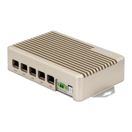
- Page 1 BOXER-8230AI Compact Fanless Embedded AI@Edge Box PC with NVIDIA® Jetson™ TX2 NX User’s Manual 1 Last Updated: June 23, 2021...
- Page 2 AAEON assumes no liabilities resulting from errors or omissions in this document, or from the use of the information contained herein. AAEON reserves the right to make changes in the product design without notice to its users.
- Page 3 Acknowledgements All other products’ name or trademarks are properties of their respective owners. NVIDIA, the NVIDIA logo, and Jetson are trademarks of the NVIDIA Corporation ⚫ ITE is a trademark of Integrated Technology Express, Inc. ⚫ IBM and VGA are trademarks of International Business Machines Corporation. ⚫...
- Page 4 Packing List Before setting up your product, please make sure the following items have been shipped: Item Quantity BOXER-8230AI ⚫ Power Connector ⚫ If any of these items are missing or damaged, please contact your distributor or sales representative immediately.
- Page 5 (if any), its specifications, dimensions, jumper/connector settings/definitions, and driver installation instructions (if any), to facilitate users in setting up their product. Users may refer to the product page at AAEON.com for the latest version of this document. Preface...
- Page 6 All cautions and warnings on the device should be noted. All cables and adapters supplied by AAEON are certified and in accordance with the material safety laws and regulations of the country of sale. Do not use any cables or adapters not supplied by AAEON to prevent system malfunction or fires.
- Page 7 As most electronic components are sensitive to static electrical charge, be sure to ground yourself to prevent static charge when installing the internal components. Use a grounding wrist strap and contain all electronic components in any static-shielded containers. If any of the following situations arises, please the contact our service personnel: Damaged power cord or plug Liquid intrusion to the device iii.
- Page 8 FCC Statement This device complies with Part 15 FCC Rules. Operation is subject to the following two conditions: (1) this device may not cause harmful interference, and (2) this device must accept any interference received including interference that may cause undesired operation.
- Page 9 China RoHS Requirements (CN) 产品中有毒有害物质或元素名称及含量 AAEON System QO4-381 Rev.A0 有毒有害物质或元素 部件名称 铅 汞 镉 六价铬 多溴联苯 多溴二苯 醚(PBDE) (Pb) (Hg) (Cd) (Cr(VI)) (PBB) 印刷电路板 × ○ ○ ○ ○ ○ 及其电子组件 外部信号 × ○ ○ ○ ○ ○ 连接器及线材 ○...
- Page 10 China RoHS Requirement (EN) Hazardous and Toxic Materials List AAEON System QO4-381 Rev.A0 Hazardous or Toxic Materials or Elements Component Name PCB and Components Wires & Connectors for Ext.Connections Chassis CPU & RAM HDD Drive LCD Module Optical Drive Touch Control...
-
Page 11: Table Of Contents
Table of Contents Chapter 1 - Product Specifications..................1 Specifications ......................2 Product Notice ......................4 Chapter 2 – Hardware Information ..................5 Dimensions ....................... 6 Jumpers and connectors..................8 List of Jumpers ......................9 2.3.1 Setting Jumpers ..................9 2.3.2 AT/ATX Mode Select (CN14 Pins 7-8) .......... - Page 12 3.1.1 Introduction .................... 26 3.1.2 Before You Begin ................... 27 3.1.3 Flash Image to Board ................28 Appendix A – Glue Removal Procedure ................30 Removing Glue from Your System ..............31 Preface...
-
Page 13: Chapter 1 - Product Specifications
Chapter 1 Chapter 1 - Product Specifications... -
Page 14: Specifications
Specifications System AI Accelerator NVIDIA® Jetson™ TX2 NX NVIDIA® Denver 2 (Dual-Core) Processor & ARM® Cortex® -A57 MPCore (Quad-Core) Processor System Memory 4GB 128-bit LPDDR4 @ 1600 MHz Storage Device eMMC 5.1 16GB Micro SD card slot x 1 2.5” SATA drive bay x 1 (A4 SKU only) Display Interface HDMI Type A x 1 for HDMI 2.0 Ethernet... - Page 15 Power Supply Power Requirement DC 10V~24V 2-pin terminal block ATX mode Mechanical Mounting Wall mount kit Dimensions (W x D x H) A3 SKU: 6.92” x 3.94” x 1.54” (175.8mm x 100.0mm x 39.0mm) A4 SKU: 6.92” x 3.94” x 2.41” (175.8mm x 100.0mm x 61.3mm) Gross Weight A3 SKU: 2.9 lbs.
-
Page 16: Product Notice
Model Differences: The BOXER-8230AI has two model SKUs, the BOXER-8230AI-A3 and BOXER-8230AI-A4, referenced as A3 SKU and A4 SKU, respectively. The key difference in the models is the A4 SKU features a 2.5” SATA drive bay and taller fins for heat dispersal, making the system taller overall than the A3 SKU. -
Page 17: Chapter 2 - Hardware Information
Chapter 2 Chapter 2 – Hardware Information... -
Page 18: Dimensions
Dimensions BOXER-8230AI-A3 Chapter 2 – Hardware Information... - Page 19 BOXER-8230AI-A4 Chapter 2 – Hardware Information...
-
Page 20: Jumpers And Connectors
Jumpers and connectors Chapter 2 – Hardware Information... -
Page 21: List Of Jumpers
List of Jumpers The board has a number of jumpers that allow you to configure your system to suit your application. The table below shows the function of each of the board's jumpers Label Function CN14 (Pin 7-8) AT/ATX mode select 2.3.1 Setting Jumpers You can configure your system to match the needs of your application by setting... -
Page 22: At/Atx Mode Select (Cn14 Pins 7-8)
2.3.2 AT/ATX Mode Select (CN14 Pins 7-8) The AT/ATX Mode Select functions by connecting pins 7 and 8 of CN14. To prevent damage to the system, do not connect pins 7 and 8 to any other pin. Open – AT Mode Closed –... -
Page 23: List Of Connectors
List of Connectors The board has a number of connectors that allow you to configure your system to suit your application. The table below shows the function of each of the board's connectors Label Function DC Power In Connector Jetson TX2 NX Gigabit LAN Connector i210AT Gigabit LAN Connector i210AT Gigabit LAN Connector i210AT Gigabit LAN Connector... -
Page 24: Dc Power In Connector (Cn1)
Label Function Recovery Switch Reset Switch 2.4.1 DC Power In Connector (CN1) Signal Signal PWR IN 2.4.2 LAN RJ45 Port (CN2/CN3/CN4/CN5/CN6) Signal Signal MDI0+ MDI0- MDI1+ MDI1- MDI2+ MDI2- MDI3+ MDI3- Note: CN2 is the Jetson TX2 NX Gigabit LAN port. Ports CN3, CN4, CN5, and CN6 are i210AT Gigabit LAN Ports. -
Page 25: Usb 2.0 Connector For Flash Image (Cn7)
2.4.3 USB 2.0 Connector for Flash Image (CN7) Signal Signal USB1- USB1+ Chapter 2 – Hardware Information... -
Page 26: Jetson Tx2 Nx Cpu Module Connector (Cn11)
2.4.4 Jetson TX2 NX CPU Module Connector (CN11) Chapter 2 – Hardware Information... - Page 27 Chapter 2 – Hardware Information...
-
Page 28: Rtc Battery Connector (Cn13)
2.4.5 RTC Battery Connector (CN13) Signal Signal 2.4.6 Front Panel Connector (CN14) Signal Signal Power Button Recovery Reset Latch Set Latch Set PWR LED Note: Pin 7 and 8 are used for setting AT/ATX Power Mode. See Chapter 2.3.2 for information. -
Page 29: Hdmi Connector (Cn16)
2.4.7 HDMI Connector (CN16) Signal Signal HDMI_DATA2_P HDMI_DATA2_N HDMI_DATA1_P HDMI_DATA1_N HDMI_DATA0_P HDMI_DATA0_N HDMI_CLK_P HDMI_CLK_N HDMI_SCL HDMI_SDA HDMI_PWR HDMI_HDP Chapter 2 – Hardware Information... -
Page 30: Usb 3.0 Connector (Cn17/18)
2.4.8 USB 3.0 Connector (CN17/18) Signal Signal VBUS_1 VBUS_2 (A)D- (B)D- (A)D+ (B)D+ (A)SSRX- (B)SSRX- (A)SSRX+ (B)SSRX+ (A)SSTX- (B)SSTX- (A)SSTX+ (B)SSTX+ Chapter 2 – Hardware Information... -
Page 31: Com Port Connector (Cn19/20)
2.4.9 COM Port Connector (CN19/20) RS-232 TTL UART Note: When using UART mode, RS-232 Receiver U21, U22 must be removed. Chapter 2 – Hardware Information... -
Page 32: Sata Connector (Cn25)
2.4.10 SATA Connector (CN25) Signal Signal SATA TX+ SATA TX- SATA RX- SATA RX+ Note: SATA Connector is a feature only for the A4 SKU model. Chapter 2 – Hardware Information... -
Page 33: Hardware Assembly
Hardware Assembly 2.5.1 Chassis Assembly BOXER-8230AI-A3 Chapter 2 – Hardware Information... - Page 34 BOXER-8230AI-A4 Chapter 2 – Hardware Information...
-
Page 35: Wall-Mount Assembly
2.5.2 Wall-mount Assembly BOXER-8230AI-A4 Chapter 2 – Hardware Information... -
Page 36: Sata Drive Assembly (A4 Sku)
2.5.3 2.5” SATA Drive Assembly (A4 SKU) Chapter 2 – Hardware Information... -
Page 37: Chapter 3 - Os Flash Guide
Chapter 3 Chapter 3 – OS Flash Guide... -
Page 38: Flash Os Image To System
Flash OS Image to System 3.1.1 Introduction This chapter details the steps to flashing the operating system to your BOXER-8230AI NVIDIA Jetson TX2 NX system. The operating system image can be downloaded from the product page at: https://www.aaeon.com/en/p/ai-edge-jetson-tx2-nx-boxer-8230ai After downloading the file, the filename will be formatted as follows: is OS Information. -
Page 39: Before You Begin
3.1.2 Before You Begin Before beginning the process ensure you have the following: One host PC with operating system Ubuntu 16.04 or 18.04 Operating System image downloaded to host computer USB Cable with Micro USB connector Jetson TX2 NX module; see image below for reference: Finally, on the Linux host PC, extract the image file you downloaded using the following command in terminal (remember to replace {“”} with the actual file name): Chapter 3 –... -
Page 40: Flash Image To Board
3.1.3 Flash Image to Board Step 1: Connect the host PC to the BOXER-8230AI with a Micro USB cable. Step 2: Connect the BOXER-8230AI carrier board to the power supply. Step 3: Force Recovery Mode: Press and hold the recovery key, then press the power key. - Page 41 Step 5: You can use lsusb command on host PC to check if the device is in recovery mode: The system will return the following when in recovery mode: Step 6: In terminal, enter the bootloader folder that you unzipped earlier. Step 7: Run the following command to flash the image: Step 8: Wait for the process to complete.
-
Page 42: Appendix A - Glue Removal Procedure
Appendix A Appendix A – Glue Removal Procedure... -
Page 43: Removing Glue From Your System
- Anti-static tweezers - An alcohol solution that is at least 99.5% alcohol (ethanol solution or denatured alcohol). AAEON recommends using an eye dropper or a bottle with a nozzle as in the picture below: Appendix A – Glue Removal Procedure... - Page 44 Step 1: Using an eyedropper or bottle as shown above, apply a few drops of alcohol to the glue. Step 2: Allow the alcohol to soak for 10 seconds, then use a cotton swab or cotton with anti-static tweezers to evenly rub the alcohol over the glue. Step 3: Let soak for 10 more seconds, then use anti-static tweezers to remove the glue.
- Page 45 If you encounter any issues or need support, please contact your AAEON representative or visit our Support Page at AAEON.com Appendix A – Glue Removal Procedure...
Need help?
Do you have a question about the BOXER-8230AI and is the answer not in the manual?
Questions and answers