Honeywell INNCOM e7w User Manual
Hide thumbs
Also See for INNCOM e7w:
- Installation instructions manual (13 pages) ,
- Troubleshooting manual (47 pages)

Related Manuals for Honeywell INNCOM e7w


Summary of Contents for Honeywell INNCOM e7w
- Page 1 INNCOM e7w Thermostat USER GUIDE Jan-2020 U.S. Registered Trademark 31-00302-01 Copyright © 2020 Honeywell Inc. All Rights Reserved...
- Page 2 INNCOM by Honeywell. By acceptance hereof, each recipient agrees to use the information contained herein only for the purpose anticipated by INNCOM by Honeywell, and not to dis- close to others, copy or reproduce, any part hereof without the written consent of INNCOM by Honeywell.
- Page 3 INNCOM e7w THERMOSTAT USER GUIDE Important Safety Information and Installation Precautions Read all instructions Failure to follow all instructions may result in equipment damage or a hazardous condition. Read all instructions carefully before installing equipment. Local codes and practices Always install equipment in accordance with the National Electric Code and in a manner acceptable to the local authority having jurisdiction.
- Page 4 By using this Honeywell literature, you agree that Honeywell will have no liability for any damages arising out of your use, or modification to, the literature. You will de- fend and indemnify Honeywell, its affiliates and subsidiaries, from and against any liability, cost, or damages, including attorneys’...
-
Page 5: Table Of Contents
INNCOM e7w THERMOSTAT USER GUIDE TABLE OF CONTENT ABOUT THIS GUIDE ............................................1 BJECTIVE ................................. 1 ELATED TECHNICAL LITERATURE ..........................1 BBREVIATION AND OMENCLATURE ........................1 OVERVIEW .................................................2 EATURES AND ENEFITS ............................3 PC502.4G X47) ....................3 PPLICATIONS REQUIRES NEED HELP? GET IN TOUCH ........................................3 SPECIFICATIONS ............................................4... - Page 6 INNCOM e7w THERMOSTAT USER GUIDE S5 G INDING THE ATEWAY SED BY THE E ..................... 24 S541.RF D INDING INDOW OR ALCONY WITCHES ................25 ERIFYING NSTALLED EVICES ......................25 ERIFYING NTRY EPORTING ........................26 ERIFYING UEST CCUPANCY EPORTING ......................26 SERVICE MODE FUNCTIONS .......................................
-
Page 7: About This Guide
This document is a part of the INNCOM e7w thermostat technical documentation library. Objective This document addresses two audiences • Hotel Administrator or Commissioning Engineer to install and use the INNCOM e7w thermostat end- to-end. • INNCOM engineering personnel tasked to prepare the e7w for service. -
Page 8: Overview
INNCOM e7w THERMOSTAT USER GUIDE Overview The battery-powered e7w thermostat is the latest E-Series thermostat, deliver superior con- venience, comfort and energy management for both guests and hoteliers. When coupled with a required PC502.4G and X47, the thermostat can integrate with an extensive range of INNCOM and third-party technologies, such as door locks, lighting, tablets to server-to- server integrations, and more. -
Page 9: Features And Benefits
INNCOM e7w THERMOSTAT USER GUIDE Features and Benefits • Battery operated wireless communication integrated with on-board motion, temperature, and humidity sensors. • Provides standalone or networked energy management. • Compatible with most HVAC systems found in hotel guestrooms, assisted living facilities, stu- dent housing, and more. -
Page 10: Specifications
INNCOM e7w THERMOSTAT USER GUIDE Specifications Mounting Standard US — Double Gang: Without Spacer Ring Standard US — Single Gang: Without Spacer Ring Standard UK — Single Gang: Without Spacer Ring Dimension L 120 mm x W 120 mm x H 23 mm (without spacer ring) {L 4.7 inch x W 4.7 inch x H 0.90 inch (without spacer ring)}... -
Page 11: Wireless Communication
INNCOM e7w THERMOSTAT USER GUIDE Wireless Communication Parameter Description RF Data Rate 250 kbps Antenna Type Range 70ft Transmit Power +5 dBm Receive Sensitivity -95 dBm Frequency Band 2.4 Ghz Encryption AES - 128 Protocol 802.15.4 Frequency Channels 11-26 Note: Required Deep Mesh Network 2.4 GHz... -
Page 12: System Block Diagram
INNCOM e7w THERMOSTAT USER GUIDE System Block Diagram The INNCOM Room Automation System (IRAS) displays guest services requests such as pri- vacy, makeup room, butler, and room service requests. When the e7w Thermostat is con- nected to the INNcontrol 3 or INNcontrol 5 software on a central server with the Deep Mesh Network (DMN), the e7w Thermostat supports automated Customer Relationship Manager (CRM) updating the staff reporting functions. -
Page 13: Load Center Application
INNCOM e7w THERMOSTAT USER GUIDE Load Center Application A load center application (also commonly referred to as the room controller unit or “RCU”) is designed to locate all of the devices capable of providing DC power, relay outputs, TRIAC dim-... -
Page 14: Security Requirements
INNCOM e7w THERMOSTAT USER GUIDE Security Requirements System Environmental Considerations A firewall is required to isolate the IRAS (INNCOM Room Automation System) for the hotel private net- work with the Internet. Unprotected Internet connections can expose and damage the IRAS system and facility components to cyber-attacks from third parties. -
Page 15: Network Communication Notice
INNCOM e7w THERMOSTAT USER GUIDE Honeywell has taken steps to prevent e7w PC50X device from being injected, but the mass data flow will result in loss of wireless communication bandwidth within the whole system. Regular check of the communication failure rate or response rate of IRAS devices is helpful to discover and isolate devices being attacked and stop the physical attacks in daily operation. -
Page 16: E7W Thermostat Wiring
INNCOM e7w THERMOSTAT USER GUIDE e7w Thermostat Wiring The battery powered wireless e7w functions as a programmable DDC thermostat, automati- cally adjusting FAN speeds and valves to achieve set temperature. Note: Guests can manually select heat or cool by pressing the OFF/AUTO button and cycling through OFF, AUTO, HEAT and COOL). -
Page 17: Wiring X47.H.p ( 120Vac) With E7W Thermostat
INNCOM e7w THERMOSTAT USER GUIDE Wiring X47.H.P 120VAC) with e7w Thermostat Below figure shows e7w Thermostat communication with PC502.4G room gateway and other devices (like X 47H P, 120 VAC HVAC controller) via RF Channel. Thermostat Wire Connections 31-00302-01... -
Page 18: User Interaction
INNCOM e7w THERMOSTAT USER GUIDE User Interaction Dormant Mode When the e7w thermostat is not in use by the guest for more than 5 seconds, the e7w ther- mostat turns off LCD display and keypad backlight. User Interaction Mode When a button is pressed by the user, the thermostat will then display the modes (heat and cool) and the measured temperature. -
Page 19: Display Functions
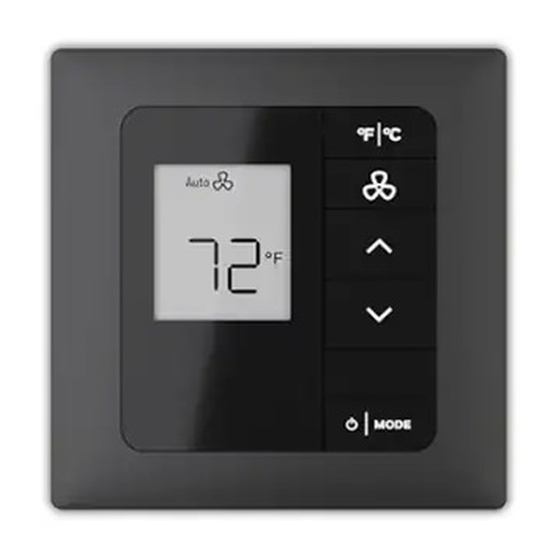
INNCOM e7w THERMOSTAT USER GUIDE S541.RF Wireless Door Switch / Transmitter 04-1096.FL e7 Remote Thermistor 201-503 PC-503 Configuration Tool used with EngINN 203-250 RS485 DM485 Communication Module 32324212-001 Thermostat Screw Kit Assembly 62-1455 Thermostat 100-277VAC Harness * Thermostat purchase includes Installation Kit, Screw Kit Assembly and Harness. - Page 20 INNCOM e7w THERMOSTAT USER GUIDE Target Temperature Displays the current value of the desired temperature (SET). Also used to display parameter in service mode. Other Temperature Displays the measured value of inside temperature, and outside temper- ature when configured. Also, it displays the parameter value in service mode.
- Page 21 INNCOM e7w THERMOSTAT USER GUIDE Measured Temperature The measured temperature icon will be displayed next to the small seven segment characters displaying the temperature when measured tem- perature is configured, or when the guest has physically interacted with the thermostat.
-
Page 22: Installation
USB cable or UART (required for firmware upgrade) Required Commissioning Tools This tool is used in conjunction with Honeywell's EngINN commissioning software, when ad- vanced commissioning of the e7w is required by a trained and certified INNCOM technician. Contact Honeywell technical support for more information. -
Page 23: Mounting Location
When the thermostat is equipped with PIR, consider view angle, range characteristics, and mounting position for proper coverage. Figure 5: Recommended mounting location e7w Setup The INNCOM e7w battery operated thermostat can be mounted on the following standard Junction • US single gang •... -
Page 24: Procedure To Setup E7W
INNCOM e7w THERMOSTAT USER GUIDE Procedure to setup e7w To mount e7w, follow the steps below: 1. Take the Smart Mounting Plate and orient it with the raised arrow embossed on mounting plate pointing UP. 2. Attach the plate to the junction box using the supplied screws as shown in Figure 5. -
Page 25: Battery Details
INNCOM e7w THERMOSTAT USER GUIDE Figure 6: e7w exploded assembly reference Battery Details Figure 7: e7w Battery Polarity Reference 1. Battery Compartment: Holds 4 AA Alkaline Batteries. 2. Insert the 4 AA alkaline batteries, matching the “+” terminals on the batteries to the “+” sym- bols in the battery compartment, as shown in Fig. -
Page 26: Initial Setup
INNCOM e7w THERMOSTAT USER GUIDE Initial Setup Before going through the initial setup sequences, ensure that thermostat is mounted and con- nected to the smart wall plate. When you run the newly programmed e7w, it will proceed into Initialization Mode In the Initial- ization Mode you need to configure Room ID, PAN ID and RF Channel in the e7w. - Page 27 INNCOM e7w THERMOSTAT USER GUIDE Note: The five-digit number is comprised of three fields — high value (HI), medium value (MED), low value (LO) (HI | MED | LO) 2. Set the High value (HI) — Three fan dots indicate high value displayed with 06 as a default value.
-
Page 28: Setup Pa Nid
INNCOM e7w THERMOSTAT USER GUIDE 5. Press MODE button to store the new Room ID number scrolling across the display. The unit beeps to confirm the value is stored in memory. Once the scrolling is completed, the screen displays rld. -
Page 29: Service Mode
INNCOM e7w THERMOSTAT USER GUIDE 2. Use UP/DOWN arrows to change value (ranging from 11 to 26). 3. Press FAN, the unit beeps to confirm the value stored in the memory and display back to rF. 4. Press MODE to check the rF value. -
Page 30: Verifying Hvac Partner Address (Pa)
INNCOM e7w THERMOSTAT USER GUIDE Verifying HVAC Partner Address (PA) The default e7w partner address is 13, and the default HVAC partner address (X47 or similar) is 14. It attempts to communicate with its HVAC partner assuming this address. Depending on the require- ment, the HVAC partner could use a different address, such as 224, to change HVAC partner address, refer Installation/ Commissioning document. -
Page 31: Binding S541.Rf Door, Window Or Balcony Switches
INNCOM e7w THERMOSTAT USER GUIDE 7. Press FC button twice to exit SERVICE MODE. NOTE: For more details, refer applicable commissioning document. Binding S541.RF Door, Window or Balcony Switches To communicate with any in-room RF devices like an S541.RF Door, Window or Balcony switches. -
Page 32: Verifying Entry Door Reporting
INNCOM e7w THERMOSTAT USER GUIDE The e7w will continuously send four read commands to read the below values from the tar- get device until the FC button is pressed. A successful ping will show the following four parameter values in sequence: 1. -
Page 33: Service Mode Functions
INNCOM e7w THERMOSTAT USER GUIDE Service Mode Functions Menu Item Description Value Use to configure the Room ID. 0 to 65535 Use to configure the ZigBee pan used in radio communications. 0 to 255 Use to configure the channel used for IRAS communications. - Page 34 INNCOM e7w THERMOSTAT USER GUIDE Menu Item Description Value Use to configure Forward and Reverse binding. e7w supports binding and configuration for both RF devices (S541.RF Door, 0 to 255 Window or Balcony switches) and Non-RF S5 bus connected de- vices (PC502.4G).
-
Page 35: Rid - Setting E7W Room Id (Rld)
INNCOM e7w THERMOSTAT USER GUIDE RID – Setting e7w Room ID (rld) 1. Enter SERVICE MODE 2. Once rld and "—"is displayed, press the MODE button. The default 65535 Room ID will scroll across the screen — one numerical setting at a time, from highest to lowest (extreme left to right value). - Page 36 INNCOM e7w THERMOSTAT USER GUIDE Medium Value 5. Set the Low value (LO) — Single fan dots indicate low value displayed with 35 as a default value. Use UP/DOWN arrow button to change the value (range is 0-99) Low Value 6.
-
Page 37: Pan - Setting E7W Pan Id (Pan)
INNCOM e7w THERMOSTAT USER GUIDE PAN – Setting e7w PAn ID (PAn) 1. Enter SERVICE MODE, 2. Use the UP/DOWN arrow buttons to select PAn and then press MODE. 3. The current PAn value will be displayed on the screen. -
Page 38: Adr - Teachinga Device Address (Adr )
INNCOM e7w THERMOSTAT USER GUIDE 6. Press the FC button to return to SERVICE MODE or press UP arrow button to display next mode. Press the FC button twice to exit SERVICE MODE ADR – Teaching A Device Address (Adr) Adr parameter is used to bind the target device to the Room ID, PAN ID, and RF channel configured in the e7w, while at the same time setting the target device address to the displayed Adr value. -
Page 39: Forward Binding
INNCOM e7w THERMOSTAT USER GUIDE a) After pressing FAN button, "bnd" will appear on the e7w display. b) Press Bind button on target device, to make the target device send a Reverse Bind Request to e7w. c) Upon receiving the Reverse Bind Request, the e7w send a Bind offer to the target device. -
Page 40: Io - Teaching A Device I/O Map (Io)
INNCOM e7w THERMOSTAT USER GUIDE Press the FC button twice to exit SERVICE MODE NOTE: For more details, refer applicable commissioning document. IO – Teaching A Device I/O Map (Io) The Io parameter is used to bind the target device to the Room ID, PAN ID, and RF channel configured in the e7w, while at the same time activating an I/O Map in the target device. -
Page 41: Reverse Binding
INNCOM e7w THERMOSTAT USER GUIDE 6. Press FAN to initiate a reverse bind, Press MODE to initiate a forward bind Reverse Binding Reverse binding is supported by device such as PC502.4G, S541.RF, K594/K595.RF. To configure reverse binding, follow the steps below. - Page 42 INNCOM e7w THERMOSTAT USER GUIDE c) After receiving the Forward Bind Request, the target device flashes LED confirm- ing that it receives the Forward Bind Request. • For binding RF devices, press bind button on the target device two times quickly, then press and hold bind button for 5-7 seconds to ac- cept the bind request.
-
Page 43: Reg - Cbl32 Registry Edit (Reg)
INNCOM e7w THERMOSTAT USER GUIDE REG – CBL32 Registry Edit (rEG) Use the rEG mode to view or edit CBL32 Registry Group 9 Thermo/HVAC and Registry Group 7:X:Y Input/output in the HVAC Partner device (i.e. X47) to the e7w. 1. Enter SERVICE MODE 2. -
Page 44: If Group 9 Thermo/Hvac Selected As The Gr. (Group) In Step 4
INNCOM e7w THERMOSTAT USER GUIDE If Group 9 Thermo/HVAC selected as the Gr. (Group) in step 4: Group 9 has no Index values, so the e7w will immediately send a 00018C09YY0000 Read Registry 09: YY Offset 0 command (YY = the Key value defined in step 6) to the address of the HVAC partner to ver- ify the selected Registry 09: YY exists. -
Page 45: If Group 7 Input/Output Selected As The Gr. (Group) In Step 4
INNCOM e7w THERMOSTAT USER GUIDE If Group 7 Input/Output selected as the Gr. (Group) in step 4: Group 7 registry's have an Index value that must be defined before defining the desired Offset, so af- ter pressing the MODE button, (I dX or Index) and 0 will be displayed. - Page 46 INNCOM e7w THERMOSTAT USER GUIDE 8. With the value of the defined Registry Offset now displayed, use the Up/Down arrow but- tons to change the value if desired. In order for any change to be permanent, you must press the FAN button to store the change.
- Page 47 INNCOM e7w THERMOSTAT USER GUIDE The following is a complete example of reading and changing a Group 9 Registry. Read Registry 9:1 Occupancy, Offset 8 Min_GuestOccupancyTimeout of the HVAC partner to the e7w. Change from the current value of 10 minutes to 15 minutes.
- Page 48 INNCOM e7w THERMOSTAT USER GUIDE The following is a complete example of reading and changing a Group 7 Registry. Read Registry 7:3:1 Light Output, Offset 20 Minlevel of an X45RA Address 30. Lower the current value of 40 to 20. In order to read the X45RA, which is not the HVAC partner to the e7w, you will need to change the current e7w Partner Address (PA) of 14 to 30, make the change to the X45RA, then change the e7w back to the original address of the e7w HVAC partner (14).
- Page 49 INNCOM e7w THERMOSTAT USER GUIDE Press F/C button to exit back to reG (rE6) and press F/C again to get Str (Store) on the display. Press FAN button to store the change. The e7w will RESET and exit Service Parameter...
-
Page 50: Png - Verifying Device Communication (Png)
INNCOM e7w THERMOSTAT USER GUIDE PNG – Verifying Device Communication (PnG) Use the PnG (Ping) parameter to Ping a device with the defined address. This allows you to test, if the device is communicating directly with the e7w via RF, or if the device is communicating through S5 bus to an installed RF device. -
Page 51: Rh - Measuring Room Humidity (Rh)
INNCOM e7w THERMOSTAT USER GUIDE If no replies are received for the read commands, the display will continue to show the P5 address to be pinged and Value. 6. Press the FC button to stop the Ping. 7. Press the FC twice button to return SERVICE MODE or press UP arrow button to dis- play next mode. -
Page 52: Rst - Resetting E7W (Rst)
INNCOM e7w THERMOSTAT USER GUIDE RST – Resetting e7w (rSt) rSt parameter is used to reset the e7w, reboot the e7w back to Factory default settings or Reset a remote device. 1. Enter SERVICE MODE 2. Press UP/DOWN arrow buttons to select rSt. -
Page 53: Dor - Verifying Door Position (Dor)
INNCOM e7w THERMOSTAT USER GUIDE 3. Press MODE button to start the test. don (Done) will briefly display, then the e7w broadcasts a Commissioning Request into the room. The device in the room with its Room Gateway function enabled then forwards the request to INNCOM server. - Page 54 INNCOM e7w THERMOSTAT USER GUIDE • A device in the room that has its “P5 Door Server” enabled that reports a 0x0002981 “Door Server Reports Door is Open” when it sees the 0x000281 Entry Door Open message. This device will typically be the room HVAC controller (X47 or similar).
-
Page 55: Pir - Verifying Motion Sensor (Pir)
INNCOM e7w THERMOSTAT USER GUIDE 4. Close the door, the e7w buzzer stops. 5. Press the FC button to return SERVICE MODE or press UP arrow button to display next mode. Press the FC button twice to exit SERVICE MODE PIR –... -
Page 56: Win - Verifying Window Position (Win)
INNCOM e7w THERMOSTAT USER GUIDE 5. The PIr motion test is active for one minute, then automatically timeout. 6. Press the FC button to return SERVICE MODE or press UP arrow button to display next mode. Press the FC button twice to exit SERVICE MODE WIN –... -
Page 57: Bnd - Binding Auxiliary Devices (Bnd)
INNCOM e7w THERMOSTAT USER GUIDE 3. Press MODE button. This action display Win value (000 value displayed). 4. Open the monitored window. The following sequence should happen: a ) The device used for monitoring and reporting window door position sends a 0x0002A1 Window Open message into the room. - Page 58 INNCOM e7w THERMOSTAT USER GUIDE 5. Press the FC button to return to Adr and “- - “on the display. 6. Press UP/DOWN arrow buttons to select the bnd parameter 7. Press MODE button. This action displays bnd value. 8. Use the UP / DOWN arrow buttons to change the value to the Address of the PC502, Evora or device that is the RF lock proxy.
-
Page 59: Ver - Verifying E7W Version (Ver)
INNCOM e7w THERMOSTAT USER GUIDE 9. Press FAN button to make the e7w send an Open Bind window command to the defined address from step 8. The command makes the target device to open a two minute bind window. You must com- plete the bind process within the 2 minutes. -
Page 60: Prr - Remote Motion Sensor (Prr)
INNCOM e7w THERMOSTAT USER GUIDE PRR – Remote Motion Sensor (Prr) Use Prr mode to test the functionality of a PIR Motion sensor connected to an INNCOM room device, such as an X05B. For this test, the e7w looks for 0x000351 PIR Active and 0x000350 PIR In-Active messages being sent from the INNCOM in-room device with externally connected motion sensor. -
Page 61: Bau - E7W Battery Level (Bau)
INNCOM e7w THERMOSTAT USER GUIDE BAU – e7w Battery Level (bAu) Use bAu mode to view the battery level of the 4 AA batteries installed in the e7w. The value is reported as a 0-255 value, which is scaled to the 0-6.4 VDC of 4 batteries, each with 1.6-volt AA battery. -
Page 62: Ser - Service Parameter (Ser)
INNCOM e7w THERMOSTAT USER GUIDE SER – Service Parameter (Ser) Ser mode is used to execute “Run” menu parameters of the CBL32 partner device, such as a X47. 1. Enter SERVICE MODE 2. Press UP/DOWN arrow buttons to select Ser. - Page 63 INNCOM e7w THERMOSTAT USER GUIDE Value Value Change value to 5 using Change the desired Run Press FAN button to Up Arrow Parameter value to 10 using the execute Up/Down buttons. Press MODE Below is a trace capture of the e7w (13) sending the command to the HVAC Partner (14) to execute Run Menu 10 with value 5: 7.
-
Page 64: P5C - P5 Channel Parameter (P5C)
INNCOM e7w THERMOSTAT USER GUIDE P5C – P5 Channel Parameter (P5C) Use P5c mode to view or set the P5 Channel of e7w. It is by default set as 1. All INNCOM devices have a P5 Channel setting that can be set from 1 to 7. This setting can be used to segregate devices so that only certain devices can communicate with other certain devices. -
Page 65: Pi5 - Process Image Viewer Parameter (Pi5)
INNCOM e7w THERMOSTAT USER GUIDE 3. Press MODE button. This action displays PA value (14 displayed as default PA value). 4. Use the UP/DOWN arrow buttons to change the PA value. 5. Press the FAN button to store the value. The e7w play beep sound. - Page 66 INNCOM e7w THERMOSTAT USER GUIDE 4. Use the UP/DOWN arrow buttons to change the Pi5 offset value over the range 0-31. If go- ing up from 0, the displayed value will roll back to 0 after 31 is reached, if going down from 31, the displayed value will roll back to 31 after 0 is reached.
-
Page 67: E7W - E7W Address Parameter (E7W)
INNCOM e7w THERMOSTAT USER GUIDE E7W – e7w Address Parameter (E7W) The local address of e7w is by default 13 If required to change the e7w local address, use E7W pa- rameter. You would need to change the e7w local address if it was required to have more than one e7w installed in the same room. - Page 68 INNCOM e7w THERMOSTAT USER GUIDE 1. Enter SERVICE MODE 2. Press UP/DOWN arrow buttons to select OAT. 3. Press MODE button. By default, the ability of the e7w to display outside air temperature is disabled and “n” (no) will displayed.
-
Page 69: Pft - E7W Pir Motion Sensor Filter (Pft)
INNCOM e7w THERMOSTAT USER GUIDE PFt – e7w PIR Motion Sensor Filter (PFt) Use the PFt parameter to adjust the sensitivity of the e7w built in PIR motion sensor. 1. Enter SERVICE MODE 2. Press UP/DOWN arrow buttons to select PFt 3. - Page 70 INNCOM e7w THERMOSTAT USER GUIDE 3. Press MODE button. This action display “- “. 4. Use UP/DOWN arrow buttons to select the target temperature (range from Off, 65 to 80 F), that will be maintained by the e7w, while in contractor mode.
- Page 71 INNCOM e7w THERMOSTAT USER GUIDE Press any key to change set temperature, fan speed or mode and you will see that the ability to change these values are locked out. To exit CONTRACTOR MODE 1. Enter SERVICE MODE 2. Press UP/DOWN arrow buttons to select Ctr “- - “...
-
Page 72: Binding And Testing Rf Locks Using E7W
INNCOM e7w THERMOSTAT USER GUIDE Binding and Testing RF Locks Using e7w Saflok RF Locks 1. Verify the Inncom Room Gateway / Saflok Proxy device is configured to support Saflok. Either verify the software created for the Inncom Proxy has default support to be the Saflok RF Lock Proxy or activate the applicable I/O Map in the device to configure it to be the Saflok RF Lock proxy. -
Page 73: Timelox Rf Locks
INNCOM e7w THERMOSTAT USER GUIDE Timelox RF Locks 1. Verify the Inncom Room Gateway / Timelox Proxy device is configured to support Timelox. Either verify the software created for the Inncom Proxy has default support to be the Timelox RF Lock Proxy or activate the applicable I/O Map in the device to configure it to be the Time- lox RF Lock proxy. -
Page 74: Salto Rf Locks
INNCOM e7w THERMOSTAT USER GUIDE Salto RF Locks 1. Verify the Inncom Room Gateway / Timelox Proxy device is configured to support Salto. Either verify the software created for the Inncom Proxy has default support to be the Salto RF Lock Proxy or activate the applicable I/O Map in the device to configure it to be the Salto RF Lock proxy. -
Page 75: Firmware Upgrade
INNCOM e7w THERMOSTAT USER GUIDE Firmware Upgrade NOTE: While updating the firmware, make sure the device and the PC is connected with the USB or UART cable. Sometimes, the operator not able to decide, if the device is in firmware state or in the se- curity bootloader state. - Page 76 INNCOM e7w THERMOSTAT USER GUIDE 4. Click Write Firmware. This action starts firmware upgrade. This action completes upgrade. After all of the selected firmware is updated. EngINN tool sends End OTW command to the e7w to indicate, that the OTW process is finished. After receiving the End OTW command, the e7w reply an acknowledgement to EngINN and restart.
- Page 77 The material in this document is for information purposes only. The content and the product described are subject to change without notice. Honeywell makes no representations or warranties with respect to this document. In no event shall Honeywell be liable for technical or editorial omissions or mistakes in this document, nor shall it be liable for any damages, direct o r incidental, arising out of or related to the use of this document.
Need help?
Do you have a question about the INNCOM e7w and is the answer not in the manual?
Questions and answers