Table of Contents
Advertisement
Quick Links
Download this manual
See also:
Manual
Advertisement
Table of Contents

Subscribe to Our Youtube Channel
Related Manuals for mikroElektronika Multimedia PIC32MX7


Summary of Contents for mikroElektronika Multimedia PIC32MX7
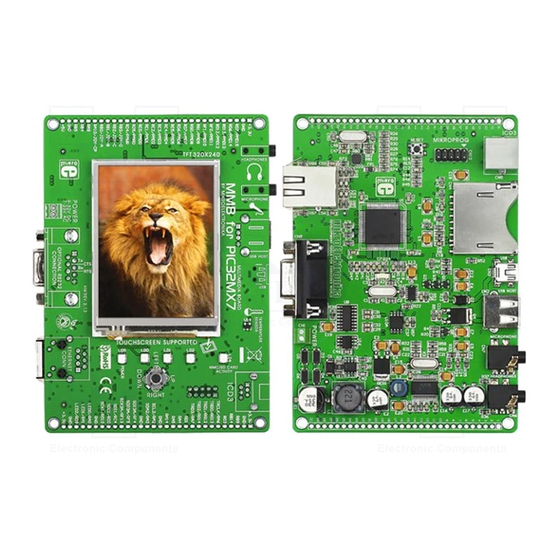
- Page 1 multime ia for PIC32MX7 Compact development system rich with on-board peripherals for all-round multimedia development on PIC32MX795F512L...
- Page 2 TO OUR VALUED CUSTOMERS I want to express my thanks to you for being interested in our products and for having confidence in Mikroelektronika. The primary aim of our company is to design and produce high quality electronic products and to constantly improve the performance thereof in order to better suit your needs.
-
Page 3: Table Of Contents
Table of Contents Introduction to MMB for PIC32MX7 6. Temperature sensor Package contains 7. Flash Memory Key Features 8. EEPROM Memory System Specification 9. MMC/SD Card Slot 1. Connecting power supply 10. Audio Module Via USB MINIB connector 11. Joystick Via screw terminal 12. -
Page 4: Introduction To Mmb For Pic32Mx7
The central part of the system is a 32- PIC32MX795F512L microcontroller that is programmed with bootloader or with external programmer mikroProg (mikroElektronika), or ICD3® (Microchip®). The MMB for PIC32MX7 features integrated modules such as audio module, 320x240 touch screen display, connector for communication with the... -
Page 5: Package Contains
Damage resistant MMB for PIC32MX7 CD with documentation protective box development system and examples MMB for PIC32MX7 MMB for PIC32MX7 USB cable user’s guide schematic Page 5... -
Page 6: Key Features
Pads TFT 320x240 display Temperature sensor Indication LEDs Joystick RESET button 2x5 male header for mikroProg programmer ICD3 connector Ethernet connector PIC32MX795F512L MicroSD Card Slot RS-232 connector USB MINIB connector USB HOST connector 3.5mm microphone connector Audio module 3.5mm headphone connector Page 6... -
Page 7: System Specification
System Specification power supply Over a USB cable (5V DC) or via screw terminal (7-23V AC or 9-32V DC) power consumption 50mA in idle state (when on-board modules are off) board dimensions 12.6 x 8.9cm (4.9 x 3.5 inch) weight ~200g (0.5 lbs) Page 7... -
Page 8: Connecting Power Supply
Via USB MINIB connector Connect the development system to a PC via a USB cable, Figure 1-1. The TFT display and Figure 1-1: Powering the POWER LED will be automatically turned on. development system via USB MINIB connector Page 8... -
Page 9: Via Screw Terminal
Via screw terminal Instead of using power supply via USB MINIB connector, it is also possible to Figure 1-2: Powering the use AC/DC power supply via screw terminal CN1. Connected power supply development system via screw source voltage can vary from 9 to 32V DC and from 7 to 23V AC. terminal CN1 Page 9... -
Page 10: Programming With Bootloader
step 1 – Connecting PIC32MX7 For programming, microcontroller use bootloader program which is preinstaled in to MCU memory. To transfer .hex file from a PC to (mikroBootloader USB HID) MCU you need bootloader software which can be downloaded from: http://www.mikroe.com/eng/products/view/573/ multimedia-board-for-pic32mx7/ After software is downloaded unzip it to desired location and start mikroBootloader USB HID software. -
Page 11: Step 2 - Browsing For .Hex File
step 2 – Browsing for .hex file step 3 – Select .hex file Figure 2-2: Browse for HEX Figure 2-3: Selecting HEX Click on Browse for HEX button Select .hex file via open window Click on Open button Page 11... -
Page 12: Step 4 - .Hex File Uploading
step 4 – .hex file uploading Figure 2-4: Begin uploading Figure 2-5: Progress bar To start .hex file uploading click on Begin uploading button You can monitor .hex file uploading via progress bar Page 12... -
Page 13: Step 5 - Finish Upload
step 5 – Finish upload Figure 2-6: Restarting MCU Figure 2-7: mikroBootloader ready for next job To finish uploading click on OK button Page 13... -
Page 14: Programing With Mikroprog™ Programmer
mikroProg The microcontroller can be programmed with programmer. The mikroProg programmer is connected to the development system via the CN10 connector, Figure 3-1. Figure 3-1: Connecting mikroProg programmer In order to connect the mikroProg programmer to the development system, it is necessary to place IDC10 connector on 2x5 male header CN10. -
Page 15: Mikroprog Features
mikroProg features: Fast mikroICD In-Circuit Debugger Support for over 600 PIC, dsPIC and PIC32 devices Compatible with mikroC, mikroBasic and mikroPascal compilers for PIC, dsPIC and PIC32 Elegant minimalistic design, clean matte white plastic finish and color indicator LEDs Page 15... -
Page 16: Programing With Icd3 Programmer
The microcontroller can be also programmed with ICD3 programmer. This programmer is connected to PIC32MX7 board via on-board ICD connector CN5. ICD3 In order to make connection between programmer and PIC32MX7 place programmers cable in to ICD connector CN5, Figure 4-1. To use ICD3 programmer it is necessary to instal program MPLAB on a PC. - Page 17 VCC3 10uF VCC3 RG15 RC14 MCLR# VCC3 RC13 RD11 RD10 RA15 RJ11 RA14 VCC3 OSC2 PIC32MX795F512L MCLR# MCLR OSC1 10 K 10 K VCC3 RESET VCC3 100nF VUSB VBUS VCC-3.3 VCC-3.3 MCLR# Figure 4-2: Connectors CN5 and VCC3 VCC3 VCC3 CN10 connection schematic CN10 note...
- Page 18 The development system features a 320x240 display covered with a resistive touch panel. Together they form a functional unit called a touch screen. It enables data to be entered and displayed at the same time. The way of entering and displaying data depends on the program loaded into the microcontroller.
- Page 19 Figure 5-2: Touch Screen connection schematic Page 19...
-
Page 20: Temperature Sensor
The built in temperature sensor (MCP9700A) is capable for measuring +125°C with accuracy of +/-2°C. temperature in range between Figure 6-1: Temperature sensor is attached to MCU via pin (TEMP). MCP9700A Page 20... - Page 21 Figure 6-2: Temperature sensor connection schematic Page 21...
-
Page 22: Flash Memory
Figure 7-1: Flash memory module Since multimedia applications are getting increasingly demanding, it is necessary to provide additional memory space to be used for storing programs by the microcontroller. The flash memory module enables the microcontroller to 8Mbit use additional flash memory. - Page 23 VCC3 10uF RG15 RC14 VCC3 RC13 R18 27 SDO1 RD11 R19 27 SCK1 RD10 EE-CS# SDI1 RA15 VCC3 RA14 PIC32MX795F512L OSC2 MCLR OSC1 100nF VCC3 VCC3 VCC3 VCC3 VUSB 100K VBUS U10A EE-CS# R22 27 SDI1 HOLD SCK1 VCC3 SDO1 VCC3 VCC3 VCC3...
-
Page 24: Eeprom Memory
Figure 8-1: EEPROM memory module EEPROM (Electrically Erasable Programmable Read-Only Memory) is a built-in memory module used for storing data that should be saved when power goes off. The 24AA01 circuit may store 1Kbit data and uses serial communication to exchange data with the microcontroller. Page 24... - Page 25 Figure 8-2: EEPROM memory module connection schematic Page 25...
-
Page 26: Mmc/Sd Card Slot
Figure 9-2: Figure 9-1: Inserting microSD card microSD card There is a built-in MMC/SD slot for MMC/SD card provided on the development system. It enables the system to additionally expand available memory space. The Serial Peripheral Interface (SPI) is used for communication between the microcontroller and MMC/SD card. Page 26... - Page 27 Figure 9-3: MMC/SD slot connecting schematic Page 27...
-
Page 28: Audio Module
The Multimedia Board features an audio module providing an interface for a microphone and stereo headphones. This module enables audio recording via a mono microphone. The microphone is connected to 3.5mm Stereo the system via a connector CN7. headphones are used for audio reproduction. They are connected to the system via a 3.5mm connector CN6. - Page 29 CDC-CS# SDA2 SCL2 VCC3 10uF VCC3 VCC3 22pF DBVCC DGND RG15 RC14 12.288MHz VCC3 CLKOUT DCVCC RC13 SCK3A BCLK 22pF SDO3A RD11 DACDAT XTI/MCLK RD10 SCL2 DACLRC SCLK SDI3A SDA2 ADCDAT SDIN RA15 CDC-CS# ADCLRC RA14 HPVDD MODE PIC32MX795F512L OSC2 LHPO LHPOUT LLINEIN...
-
Page 30: Joystick
Figure 11-1: Joystick with taster function Use built-in joystick make simple games, menus and other applications that requires movement in four directions with taster function (when joystick is pressed). Page 30... - Page 31 Figure 11-2: Joystick connecting schematic Page 31...
-
Page 32: Usb Connectors
MultiMedia Board for PIC32MX7 have two USB connectors: USB MINIB and USB HOST. USB MINIB represents OTG device which is used for connection Figure 12-1: Inserting with a PC. This USB connector is used for MCU programming the USB MINIB cable via bootloader software. - Page 33 Figure 12-2: MMB for PIC32MX7 connected with USB device via USB cable USB HOST (USB A) connector is used for attaching another devices to MMB for PIC32MX7 board like printer, scanner, keyboard etc. Bare in mind that is Figure 12-3: Inserting the USB cable in USB HOST necessary to write a program...
- Page 34 Figure 12-4: USB connectors connecting schematic Page 34...
-
Page 35: Indication Leds
(Light-Emitting Diode) is a highly efficient electronic source of light. When connecting LEDs, it is necessary to use a current limiting resistor. A common LED diode voltage is approximately 2.5V, while the current varies from 1 to 20mA depending on the type of LED. The Multimedia Board uses LEDs with current I=1mA. -
Page 36: Rs-232 Module
The development board features the RS-232 module which communicates with MCU via UART communication. UART (Universal Asynchronous Receiver/Transmitter) is one of the most common ways of exchanging data between a PC and peripheral devices. The RS-232 serial Figure 14-1: Connecting communication is performed via a 9-pin SUB-D connector and... - Page 37 Figure 14-2: RS-232 module connecting schematic Page 37...
-
Page 38: Ethernet Module
Figure 15-2: Ethernet cable connected with board Ethernet module, development system can access the LAN network in order to establish communication with remote devices. The Ethernet module operates IEEE 802.3/802.3u in compliance with the ISO 802-3/IEEE 8021.3 (10BASE-T) standards. The Figure 15-1: Inserting development system is connected to the network via... - Page 39 VCC3 10uF AERXERR RG15 RC14 VCC3 RC13 AEMDC RD11 RD10 AEMDIO AETXEN Figure 15-3: Ethernet module RA15 RA14 connecting schematic AECRSDV PIC32MX795F512L OSC2 MCLR OSC1 AEREFCLK VCC3 AERXD0 VCC3 AERXD1 VCC3 VUSB VBUS AEMDC VCC3 VCC3 VCC3 VCC3 AEMDIO VDD1A MDIO CRS_DV AERXERR...
-
Page 40: Accelerometer
Figure 16-1: Accelerometer The accelerometer is used to measure acceleration, orientation, gravity, etc. The accelerometer’s function is defined by the user in the program loaded into the microcontroller. Communication between the accelerometer and the microcontroller is performed via the interface. Page 40... - Page 41 Figure 16-2: Accelerometer connection schematic Page 41...
-
Page 42: Pinout
Pin functions Pin functions VCC3 +3.3V power supply +3.3V power supply VCC3 Ground Ground USB-PSW PMD15 RB14 LCD-CS# PMD14 Digital I/O PMD13 RD13 TRCLK Trace data clock PMD12 RD12 RG13 TRD0 PMD11 RG12 TRD1 PMD10 Trace data bits TRD2 RG14 PMD9 TRD3 PMD8... -
Page 43: Pads
VCC3 VCC3 VCC3 HDR1 HDR2 10uF 100nF PMD15 USB-PSW AERXERR RG15 PMD14 LCD-CS# VCC3 SOSCO VCC3 RC14 PMD13 SOSCI PMD5 RC13 PMD12 TRCLK R8 27 PMD6 SDO1 PMD11 TRD0 PMD7 AEMDC RD11 PMD10 TRD1 100nF R19 27 LCD-RST SCK1 RD10 PMD9 TRD2 EE-CS#... -
Page 44: Pic32Mx795F512L Microcontroller
The mikromedia for PIC32 development system comes with the PIC32MX795F512L 32-bit microcontroller. This high-performance microcontroller with its integrated modules and in combination with other on-board modules is ideal for multimedia applications. Key microcontroller features - 1.56 DMIPS/MHz, 32-bit MIPS M4K Core; - 512K Flash (plus 12K boot Flash);... -
Page 45: Dimensions
8.31mm (0.34") 69.23mm (2.72") 125.71mm (4.94") 5.51mm 15.93mm 20.96mm 31.02mm (1.22") 13.14mm 0.21") (0.51") (0.62") (0.82") 125.71mm (4.94") 118.11mm (4.65") 14.25mm (0.56") 14.25mm (0.56") 9.34mm 14.46mm 8.50mm 7.70mm (0.36") (0.56") (0.33") (0.30") 28.39mm (1.11") Tolerance +/- 1mm (0.04") 4.72mm 9.95mm 4.60mm 14.46mm (0.56") 6.25mm... - Page 46 Notes: Page 46...
- Page 47 No part of this manual, including product and software described herein, may be reproduced, stored in a retrieval system, translated or transmitted in any form or by any means, without the prior written permission of MikroElektronika. The manual PDF edition can be printed for private or local use, but not for distribution.
- Page 48 If you want to learn more about our products, please visit our website at www.mikroe.com If you are experiencing some problems with any of our products or just need additional information, please place your ticket at www.mikroe.com/en/support If you have any questions, comments or business proposals, do not hesitate to contact us at office@mikroe.com...
- Page 49 Mouser Electronics Authorized Distributor Click to View Pricing, Inventory, Delivery & Lifecycle Information: mikroElektronika MIKROE-596...
Need help?
Do you have a question about the Multimedia PIC32MX7 and is the answer not in the manual?
Questions and answers