Table of Contents
Advertisement
Quick Links
Download this manual
See also:
User Manual
Advertisement
Table of Contents

Related Manuals for mikroElektronika mikromedia+ for PIC32MX7


Summary of Contents for mikroElektronika mikromedia+ for PIC32MX7
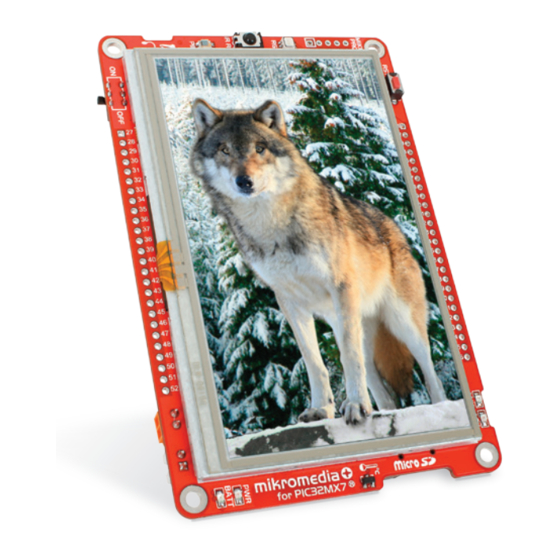
- Page 1 mikromedia+ for PIC32MX7 ® Amazingly compact, all-on-single-pcb development board carring 4.3’’ TFT Touch Screen and lots of multimedia peripherals, all driven by powerful PIC32MX795F512L microcontroller.
- Page 2 TO OUR VALUED CUSTOMERS I want to express my thanks to you for being interested in our products and for having confidence in MikroElektronika. The primary aim of our company is to design and produce high quality electronic products and to constantly improve the performance thereof in order to better suit your needs.
-
Page 3: Table Of Contents
Table of Contents Introduction to mikromedia+ for PIC32MX7 6. Port Expander ® System Specification 7. MicroSD Card Slot Package Contains 8. Touch Screen 1. Power Supply 9. Audio Module 2. PIC32MX795F512L Microcontroller 10. USB DEVICE Connection Key Microcontroller Features 11. USB HOST Connection 3. -
Page 4: Introduction To Mikromedia+ For Pic32Mx7
Introduction to mikromedia+ for PIC32MX7 ® System Specification mikromedia+ for PIC32MX7 is a compact development ® system which allows development of devices with multimedia contents. The central part of the system is a 32-bit 100-pin power supply PIC32MX795F512L microcontroller. The mikromedia+ for... -
Page 5: Package Contains
PRODUCT DVD www.mikroe.com www.libstock.com Copyright ©2012 Mikroelektronika. All rights reserved. MikroElektronika, MikroElektronika logo and other MikroElektronika trademarks are the property of MikroElektronika. All other trademarks are the property of their respective owners. Unauthorized copying, hiring, renting, public performance and broadcasting of this DVD is strictly prohibited. -
Page 6: Power Supply
USB power supply Battery power supply Screw terminals power supply The mikromedia+ for PIC32MX7 board can be powered in three different ways: via USB connector using MINI-B USB cable provided with ® the board (CN4), via battery connector using Li-Polymer battery (CN5) or via screw terminals using laboratory power supply (CN3). After you plug in the appropriate power supply turn the power switch ON (SW1). - Page 7 USB-PSW USB-PSW USB-VBUS VCC-3.3V USB-VBUS USB-D_N USB-D_N USB-D_P USB-D_P USB-ID USB-ID 1.5uH Vusb_OUT VCC-5V VOUT USB-PSW VCC-5V TPS2041B PWR-EN PGND C136 100nF 10uF 100K VAUX TPS63060 C140 C141 PDTC114EU B340A PMEG3010ER 22uF 22uF 22uF 100nF 10nF 100pF 22uF 100nF 10pF Vusb_IN VBUS V_INPUT...
-
Page 8: Pic32Mx795F512L Microcontroller
2. PIC32MX795F512L Microcontroller The mikromedia+ for PIC32MX7 development board comes ® with the 100-pin PIC32MX795F512L microcontroller. This 32-bit high-performance microcontroller integrated modules, such as 512K of flash and 128K of RAM easily handling demanding applications. Key microcontroller features - Up to 125 DMIPS Operation (80MHz);... -
Page 9: Programming The Microcontroller
3. Programming the Microcontroller Figure 3-1: PIC32MX795F512L microcontroller The microcontroller can be programmed in two ways: Using USB mikroBootloader Using external mikroProg for PIC , dsPIC , PIC32 programmer ™ ® ® ® Page 9... -
Page 10: Programming With Mikrobootloader
Programming with mikroBootloader step 1 – Connecting mikromedia Microcontroller is pre-programmed with USB HID Bootloader, which can be used to upload new device firmware. To transfer firmware .HEX file from a PC to MCU you need to use mikroBoot- loader USB HID application, which can be downloaded from: http://www.mikroe.com/downloads/get/2031/mikro- media_plus_pic32mx7_bootloader.zip Upon download, unzip it to desired location and start the mikro-... -
Page 11: Step 2 - Browsing For .Hex File
step 2 – Browsing for .HEX file step 3 – Selecting .HEX file Figure 3-3: Browse for HEX Figure 3-4: Selecting HEX Browse for HEX Click the button and from a Select .HEX file from the Open dialog window. pop-up window (Figure 3.4) choose the .HEX file Click the Open button. -
Page 12: Step 4 - Uploading .Hex File
step 4 – Uploading .HEX file Figure 3-5: Begin uploading Figure 3-6: Progress bar In order to upload .HEX file click the .HEX file uploading can be monitored via progress bar. Begin uploading button. Page 12... -
Page 13: Step 5 - Finish Upload
step 5 – Finish Upload Figure 3-7: Restarting MCU Figure 3-8: mikroBootloader ready to use Click the button after uploading is finished. The board will be automatically reset and after 5 seconds your new program will be executed. Page 13... -
Page 14: Programming With Mikroprog ™ Programmer
Programming with mikroProg Programmer ™ Figure 3-9: mikroProg ™ connector mikroProg for PIC , dsPIC and PIC32 programmer mikroProg Suite The microcontroller can be programmed with external ™ ® ® ® ™ for PIC software. The external programmer is connected to the development system via 2X5 mikroProg connector, Figure 3-9. - Page 15 VCC-3.3V VCC-3.3V 10uF C111 C112 C113 100nF 100nF 100nF RG15 C109 22pF SOSCO/RC14 SOSCI/RC13 VCC-3.3V 32.768KHz C110 22pF RD11 C114 C115 C116 RD10 100nF 100nF 100nF RA15 RA14 C107 22pF OSC2/RC15 PIC32MX795F512L MCLR# MCLR OSC1/RC12 16MHz VCC-3.3V C108 22pF C117 C124 C125 100nF...
-
Page 16: Mikroprog Suite ™ For Pic ® Software
mikroProg Suite for PIC Software ™ ® PIC32 mikroProg programmer requires ™ special programming software called mikroProg Suite for PIC . It can be ™ ® used for programming all Microchip ® crocontroller families, including PIC10 ® PIC12 , PIC16 , PIC18 , dsPIC30/33 ®... -
Page 17: Software Installation Wizard
Software Installation Wizard Start Installation Accept EULA and continue Install for all users Choose destination folder Installation in progress Finish installation Page 17... -
Page 18: Reset Button
4. Reset Button The board is equipped with reset button, which is located on the front side of the board. One press on the reset button will generate a low voltage level on the microcontroller reset pin (input). Reset button can also be externally provided through the pin 27 on the side headers. - Page 19 VCC-3.3V VCC-3.3V VCC-3.3V C111 C112 C113 10uF 100nF 100nF 100nF RESET 100nF RG15 C109 22pF SOSCO/RC14 VCC-3.3V SOSCI/RC13 32.768KHz C110 22pF RD11 VCC-3.3V C114 C115 C116 RD10 100nF 100nF 100nF HDR2 RA15 RA14 C107 22pF OSC2/RC15 PIC32MX795F512L MCLR# MCLR OSC1/RC12 16MHz C108 22pF...
-
Page 20: Crystal Oscillators And 2.048V Reference
5. Crystal Oscillators and 2.048V Reference 16MHz The board is equipped with crystal oscillator (X4) circuit that provides external clock waveform to the microcontroller OSC1 and OSC2 pins. This base frequency is suitable for further clock multipliers and ideal for generation of necessary USB clock, which ensures proper operation of bootloader and your custom USB-based 32.768kHz crystal... - Page 21 VCC-3.3V VCC-3.3V 10uF C111 C112 C113 100nF 100nF 100nF C109 RG15 22pF SOSCO/RC14 SOSCI/RC13 32.768KHz C110 VCC-3.3V 22pF RD11 RD10 C114 C115 C116 100nF 100nF 100nF RA15 RA14 C107 22pF OSC2/RC15 PIC32MX795F512L MCLR OSC1/RC12 16MHz C108 22pF VCC-3.3V C117 C124 C125 D+/RG2 D-/RG3...
-
Page 22: Port Expander
6. Port Expander Figure 6-1: Port Expander mikromedia+ for PIC32MX7 ® features 16-bit port expander module MCP23S17 which communicates with PIC32MX795F512L microcontroller via SPI serial interface. This module enables you to expand the number of microcontroller I/O pins with two 8-bit I/O ports (PORTA and PORTB). - Page 23 C109 VCC-3.3V SOSCO 22pF VCC-3.3V VCC-3.3V SOSCI 10uF 32.768KHz C110 22pF 100K 100K EXP-PWM0 EXP-GPIO7 GPB0 GPA7 EXP-PWM1 EXP-GPIO6 GPB1 GPA6 EXP-PWM2 EXP-GPIO5 GPB2 GPA5 EXP-PWM3 EXP-GPIO4 GPB3 GPA4 EXP-INT0 EXP-GPIO3 GPB4 GPA3 RG15 C107 EXP-INT1 EXP-GPIO2 SOSCO OSC2 GPB5 GPA2 22pF SOSCO/RC14...
-
Page 24: Microsd Card Slot
7. microSD Card Slot Figure 7-1: The board contains microSD card slot for using microSD cards in your projects. microSD Card Slot It enables you to store large amounts of data externally, thus saving microcontroller memory. microSD cards use Serial Peripheral Interface (SPI) for communication with the microcontroller. Ferrite and capacitor are provided to compensate the voltage and current glitch that can occur when pushing- in and pushing-out microSD card into the socket. - Page 25 VCC-3.3V C111 C112 C113 C109 SOSCO 22pF 100nF 100nF 100nF SOSCI VCC-3.3V 32.768KHz C110 22pF 10uF VCC-3.3V C107 OSC2 22pF OSC1 C114 C115 C116 16MHz C108 100nF 100nF 100nF RG15 22pF SOSCO SOSCO/RC14 SOSCI SOSCI/RC13 SPI_MOSI R100 VCC-MMC RD11 SPI_SCK R101 RD10 VCC-3.3V...
-
Page 26: Touch Screen
8. Touch Screen 4.3‘‘ The development system features a TFT 480x272 display covered with a resistive touch panel. Together they touch form a functional unit called a screen, Figure 8-1. It enables data to be entered and displayed at the same time. The TFT display is capable of showing graphics in 256K... - Page 27 VCC-1.2V VCC-3.3V 10uF VCC-3.3V VDDD VDDIO VDDIO VDDD VDDD TFT-D0 TFT-D1 RG15 C109 SOSCO SOSCO 22pF VCC-3.3V VCC-1.2V TFT-D2 SOSCO/RC14 TFT-D5 SOSCI SOSCI TFT-D3 SOSCI/RC13 32.768KHz TFT-D6 TFT-D4 LCD-R2 C110 TFT-D7 LDATA18 22pF LCD-R3 RD11 VDDIO LDATA19 TFT-RST# RD10 VDDLCD 100K VDDD EN ADJ...
-
Page 28: Audio Module
9. Audio Module Figure 9-1: On-board VS1053 MP3 codec mikromedia+ for PIC32MX7 features stereo audio codec VS1053. This module ® stereo headphones with enables audio reproduction and sound recording by using microphone connected to the system via a 3.5mm connector CN2. All functions of this module are controlled by the microcontroller over Serial Peripheral Interface (SPI). - Page 29 LINE _OUT_L VCC-3.3V VCC-1.8V 10uF 100K 3.3nF C138 10uF 100nF 100nF 100nF 100nF 100nF 100nF 100nF 100nF 100nF 100nF LINE _OUT_R VCC-3.3V 10uF 100K 3.3nF 10uF VCC-3.3V MICP RG15 SOSCO SOSCO/RC14 SOSCI 100nF GBUF SOSCI/RC13 SPI_MOSI R100 VCC-3.3V RIGHT RD11 SPI_SCK R101 VCC-3.3V...
-
Page 30: Usb Device Connection
10. USB DEVICE connection Figure 10-1: Connecting USB cable to MINI-B USB connector PIC32MX795F512L microcontroller has integrated USB module, which enables you to implement USB communication functionality to your mikromedia board. Connection with target USB host is establish over MINI-B USB connector. - Page 31 VCC-3.3V VCC-3.3V 10uF C111 C112 C113 C109 SOSCO 22pF 100nF 100nF 100nF SOSCI 32.768KHz C110 22pF RG15 SOSCO SOSCO/RC14 SOSCI SOSCI/RC13 VCC-3.3V C107 RD11 OSC2 22pF RD10 OSC1 16MHz C114 C115 C116 C108 22pF 100nF 100nF 100nF RA15 RA14 OSC2 OSC2/RC15 PIC32MX795F512L OSC1...
-
Page 32: Usb Host Connection
11. USB HOST connection When the device is working in Note: USB HOST mode, it must not be mounted to other USB HOST. Figure 11-1: Connecting USB cable to MINI-B USB connector via USB adapter PIC32MX795F512L can also be used as USB HOST which enables microcontroller to establish connection with the target device (eg. - Page 33 VCC-3.3V VCC-3.3V C111 C112 C113 VCC-3.3V 100nF 100nF 100nF Vusb_OUT 10uF VCC-5V USB-PSW TPS2041B C136 100nF 10uF VCC-3.3V RG15 PDTC114EU SOSCO PMEG3010ER SOSCO/RC14 SOSCI C114 C115 C116 SOSCI/RC13 100nF 100nF 100nF RD11 Vusb_IN RD10 VBUS USB-D_N RA15 USB-D_P RA14 USB-ID 10uF 10uF OSC2...
-
Page 34: Accelerometer
12. Accelerometer Figure 12-1: On board ADXL345 accelerometer is used to measure acceleration in three Accelerometer axis: x, y and z. Most common use is to determine the screen orientation, module but there are many other fields of usage. Communication between the accelerometer and the microcontroller is performed through interface. - Page 35 VCC-3.3V VCC-3.3V VCC-3.3V I2C_SCL VCC-3.3V 10uF I2C_SDA ACCEL-ADR INT2 ACCEL-INT# INT1 RG15 SOSCO SOSCO/RC14 SOSCI ADXL345 SOSCI/RC13 RD11 RD10 VCC-3.3V VCC-3.3V VCC-3.3V RA15 ACCEL-INT# C109 RA14 C111 C112 C113 SOSCO 22pF C139 SOSCI OSC2 100nF 100nF 100nF OSC2/RC15 32.768KHz 100nF 100nF PIC32MX795F512L OSC1...
-
Page 36: Flash Memory
13. Flash Memory Since multimedia applications are getting increasingly demanding, it is necessary to provide additional memory space for storing more data. The flash memory module enables the microcontroller to use additional 8Mbit flash memory. It is connected to the microcontroller via the Serial Peripheral Interface (SPI). - Page 37 VCC-3.3V 10uF VCC-3.3V VCC-3.3V C123 100nF RG15 SOSCO SOSCO/RC14 FLASH-CS# SOSCI VCC-3.3V SOSCI/RC13 SPI_MISO SPI_MOSI R100 HOLD SPI_SCK R68 27 RD11 C111 C112 C113 SPI_MOSI SPI_SCK R101 RD10 100nF 100nF 100nF M25P80 SPI_MISO RA15 RA14 OSC2 OSC2/RC15 PIC32MX795F512L OSC1 MCLR OSC1/RC12 VCC-3.3V VCC-3.3V...
-
Page 38: Rf Transceiver
RF transceiver module RF transceiver 2.4GHz chip antenna. It is suitable for wireless operation mikromedia+ for PIC32MX7 board features chip with ® in the world wide ISM frequency band at 2.400 - 2.4835GHz with air data rate up to 2Mbps. RF transceiver module is connected to the microcontroller via the Serial Peripheral Interface (SPI). - Page 39 VCC-3.3V 10uF VCC-RF 33nF RG15 SOSCO SOSCO/RC14 Rufa_2.4GHz_LEFT SOSCI SOSCI/RC13 SPI_MOSI R100 RF-CE RD11 SPI_SCK 3.9nH R101 RF-CS# RD10 1.5pF SPI_SCK nRF24L01P ANT2 SPI_MOSI 8.2nH MOSI ANT1 SPI_MISO SPI_MISO RA15 MISO VDD_PA N.M. RA14 R88 27 2.7nH OSC2 OSC2/RC15 PIC32MX795F512L OSC1 MCLR OSC1/RC12...
-
Page 40: Ethernet Transceiver
14. Eternet Transceiver 15. Ethernet Transceiver Figure 15-1: Ethernet transceiver module The development system features an Ethernet transceiver module ideal for local area networking (LAN). Communication over Ethernet is based on data packets called frames. Each frame contains source and destination addresses and error-checking data so that damaged data can be detected and re-transmitted. - Page 41 VCC-3.3V VCC-ETH VCC-3.3V VCC-ETH 12K1 10uF C118 C131 C153 10uF 100nF 100nF 100nF LAN-RXER LAN-TXD1 RG15 TXD1 VDD2A SOSCO LAN-LED2 LAN-TXD0 SOSCO/RC14 SOSCI LED2 TXD0 LAN-LED1 LAN8720A LAN-TXEN SOSCI/RC13 LED1 TXEN LAN-RST# LAN-MDC XTAL2 nRST RD11 LAN-CLKO XTAL1 REFCLKO RD10 LAN-MDC VDDCR LAN-MDIO...
-
Page 42: Buzzer
16. Buzzer The board is also equipped with piezo buzzer. It is an electric component which can be used to create sound when is provided with electrical signal. This is usually a PWM signal coming from a microcontroller pin. Frequency of the signal determines the pitch of the sound and duty cycle of the signal can be used to increase or decrease the volume. - Page 43 VCC-3.3V VCC-3.3V 10uF C111 C112 C113 100nF 100nF 100nF RG15 C109 VCC-3.3V 22pF SOSCO/RC14 SOSCI/RC13 32.768KHz C110 C114 C115 C116 22pF RD11 RD10 100nF 100nF 100nF RA15 RA14 C107 VCC-3.3V 22pF OSC2/RC15 PIC32MX795F512L MCLR OSC1/RC12 16MHz C118 C117 C124 C125 22pF 100nF VCC-5V...
-
Page 44: Other Modules
17. Other Modules The board also contains other useful peripherals such as PIN photodiode, IR receiver, RGB led diode and analog temperature sensor. PIN photodiode is a type of photo detector. It has high sensitivity and response speed. It is connected to the microcontroller analog pin RB8. - Page 45 VCC-5V 100K 27K4 VCC-3.3V PDTC114EU AN-PD LED R VCC-3.3V U17B 150K U17A LM358 PD15 10uF C150 LM358 100nF VCC-3.3V C103 100nF VCC-5V VCC-3.3V RG15 SOSCO SOSCO/RC14 SOSCI C111 C112 C113 SOSCI/RC13 100nF 100nF 100nF RD11 PDTC114EU RD10 C109 SOSCO 22pF LED G SOSCI RA15...
-
Page 46: Pads
18. Pads Interrupt UART Analog lines 5V power Reset pin Ref. Ground 3.3V 3.3V pwr. RB11 Audio out RB12 Audio in Analog lines GPB0 GPB1 PWM Lines GPA0 GPB2 GPA1 GPB3 GPA2 GPA6 GPIO GPIO GPA3 GPA7 GPA4 GPB4 5V power GPA5 GPB5 Interrupt Lines... - Page 47 VCC-5V HDR1 VCC-3.3V HDR-AN0 HDR-AN1 HDR2 VCC-3.3V MCLR# HDR-AN2 HDR-AN3 HDR-LN_OUT_L HDR-AN4 C111 C112 C113 HDR-LN_OUT_R HDR-AN5 VCC-3.3V HDR-LN_IN_L HDR-GPIO0 100nF 100nF 100nF HDR-LN_IN_R 10uF HDR-GPIO1 HDR-PWM0 HDR-GPIO2 HDR-PWM1 HDR-GPIO3 HDR-PWM2 HDR-GPIO4 HDR-PWM3 HDR-GPIO5 HDR-GPIO6 HDR-CAN_RX HDR-GPIO7 HDR-CAN_TX HDR-INT0 HDR-SPI_SS RG15 VCC-3.3V HDR-INT1...
-
Page 48: Mikromedia+ For Pic32Mx7
19. mikromedia+ SHIELD for PIC32MX7 ® We have also made an extension board pin-compatible with your mikromedia+ board, which enables you to easily expand your basic board functionality. It is called mikromedia+ SHIELD for PIC32MX7 . The shield contains: ® FTDI USB-UART chip USB MINI-B connector CAN transceiver... - Page 49 VCC-3.3V VCC-5V VCC-3.3V VCC-5V VCC-3.3V VCC-5V VCC-3.3V VCC-5V RB11/AN1 GPB0/PWM1 RB12/AN2 GPB1/PWM2 RB1/AN3 GPB2/PWM3 RB0/AN4 GPB3/PWM4 RB6/RST1 GPB4/INT1 GPA0/RST2 GPB5/INT2 GPA2/RST3 GPB6/INT3 GPA6/RST4 GPB7/INT4 RB7/CS1 RF4/UART-RX GPA1/CS2 RF4/UART-RX RD9/CS3 RF4/UART-RX GPA7/CS4 RF4/UART-RX RD10/SPI-SCK RF5/UART-TX RD10/SPI-SCK RF5/UART-TX RD10/SPI-SCK RF5/UART-TX RD10/SPI-SCK RF5/UART-TX RC4/SPI-MISO RA2/I2C-SCL RC4/SPI-MISO...
-
Page 50: Click Boards Are Plug And Play
20. Click boards are plug and play! So far, MikroElektronika has released more than 60 mikroBUS compatible click Boards . On average, one ™ ™ click board is released per week. Our intention is to enable you to easily expand with as many add-on boards as possible, so you will be able to easily expand the functionality of your development board.Each click... - Page 51 RFid click Relay click 8X8 click FM click Bluetooth2 click Thunder click USB SPI click ™ ™ ™ ™ ™ ™ ™ BarGraph click 7seg click THERMO click Gyro click EEPROM click LightHz click Pressure click ™ ™ ™ ™ ™...
-
Page 52: Dimensions
21. Dimensions 119.54 4706 111.54 4391 7.77 72.78 2865 24.2 63.5 63 157 2600 7.99 314.5 10.16 8.38 2.54 5.59 8.64 Legend 73.56 2896 mils 81.63 3214 Page 52... -
Page 53: What's Next
GUI. It will automatically create necessary code which is compatible with MikroElektronika compilers. Visual TFT is rich with examples, which are an excellent starting point for your future projects. Just load the example, read well commented code, and check how it works on hardware. - Page 54 Notes: Page 54...
- Page 55 No part of this manual, including product and software described herein, may be reproduced, stored in a retrieval system, translated or transmitted in any form or by any means, without the prior written permission of MikroElektronika. The manual PDF edition can be printed for private or local use, but not for distribution.
- Page 56 PIC32 If you want to learn more about our products, please visit our website at www.mikroe.com If you are experiencing some problems with any of our products or just need additional information, please place your ticket at www.mikroe.com/esupport If you have any questions, comments or business proposals, mikromedia Plus for PIC32MX7 Manual ver.
Need help?
Do you have a question about the mikromedia+ for PIC32MX7 and is the answer not in the manual?
Questions and answers