mikroElektronika EasyMx PRO v7 User Manual
For tiva c series
Hide thumbs
Also See for EasyMx PRO v7:
- User manual (45 pages) ,
- Manual (5 pages) ,
- Schematics (2 pages)
Table of Contents
Advertisement
Quick Links
Advertisement
Table of Contents

Subscribe to Our Youtube Channel
Related Manuals for mikroElektronika EasyMx PRO v7


Summary of Contents for mikroElektronika EasyMx PRO v7
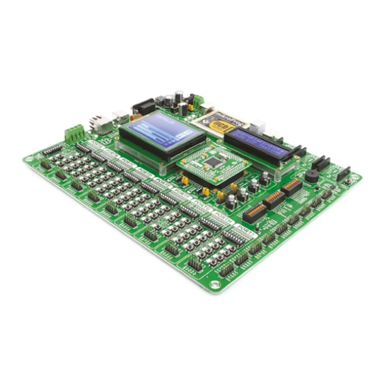
- Page 1 EasyMx PRO for Tiva C Series ™ microcontrollers supported Many on-board modules Easy-add extra boards Two connectors for each port Fast USB 2.0 programmer and The ultimate Tiva board Multimedia peripherals mikroBUS sockets Amazing Connectivity In-Circuit Debugger ™ ™...
- Page 2 To our valued customers From day one, we in MikroElektronika set ourselves the highest possible goals in pursuit of excellence. That same day, the idea for Easy development boards was born. In its each and tiniest piece we had put all our energy, creativity, and sense of what's best for an engineer.
-
Page 3: Table Of Contents
Introduction Communication Introduction ........USB-UART A . -
Page 4: Introduction
Introduction Cortex -M4 are increasingly popular microcontrollers. They are rich ® ™ with modules, with high performance and low power consumption, so creating a development board the size of EasyMx PRO v7 for Tiva ™ ™ Series was really a challenge. We wanted to put as many peripherals on the board as possible, to cover many internal modules. -
Page 5: It's Good To Know
It's good to know TM4C129XNCZAD is the default microcontroller System specification TM4C129XNCZAD is the default chip of - Great choice for both beginners power supply EasyMx PRO v7 for Tiva C Series. It belongs to ™ and professionals 7–23V AC or 9–32V DC Cortex -M4 family. -
Page 6: Power Supply
Power supply Board contains a switching power supply that creates stable voltage and current levels necessary for powering each part of the board. The power supply section contains a specialized MC34063A power regulator which creates a VCC-3.3V power supply, thus making the board capable of supporting 3.3V microcontrollers. - Page 7 Power supply: via DC connector or screw terminals The board's power supply unit creates a stable 3.3V voltage (7V to 23V AC or 9V to 32V DC), necessary for the operation of the microcontroller and all or via USB cable (5V DC) Power capacity: on-board modules.
-
Page 8: Default Mcu Card
Default MCU card Figure 4-1: Default MCU card Microcontrollers are supported using specialized 104-pin with TM4C129XNCZAD MCU cards that can be inserted into the on-board MCU socket. There are several types of cards which cover all microcontroller -M4. The Default MCU card families of Tiva ™... - Page 9 100nF 100nF 100nF 100nF 100nF 100nF 100nF 100nF 100nF 100nF 10nF 10nF VCC-CORE VREF VCC-ADC 10nF 100nF 2.2uF 100nF 10nF 100nF 10nF 10uF 10uF USB-D_P USB-D_N TM4C129XNCZAD TM4C129XNCZAD TM4C129XNCZAD LAN-RX_P LAN-RX_N LAN-TX_P LAN-TX_N RST# USB-D_P USB-D_N OSC0 VREF RST# OSC0 22pF GNDX2 GNDX2...
- Page 10 How to properly insert your MCU card into the socket? Before you plug the microcontroller card into on the EasyMx PRO v7 Tiva C Series board MCU Check again if everything is placed correctly and ™ ™ the socket, make sure that the power supply is socket.
-
Page 11: Other Supported Mcu Cards
Other supported MCU cards MikroElektronika currently offers total your own and solder any supported microcontroller in your final devices. For a complete list of currently three populated MCU cards for the EasyMX for you need in your development. There are a total... -
Page 12: On-Board Programmer
On-board programmer What is mikroProg ™ mikroProg is a fast programmer and debugger which is based on TI ICDI debugger. Smart engineering allows mikroProg ™ ™ to support over 55 ARM ® Cortex ™ -M4 devices from Tiva ™ C Series in a single programmer. It also features a powerful debugger which will be of great help in your development. -
Page 13: List Of Mcus Supported With Mikroprog
Tiva C Series ARM® Cortex -M4 microcontrollers supported with mikroProg ™ ™ ™ TM4C1230C3PM TM4C1232H6PM TM4C1237E6PZ TM4C123GH6PZ TM4C1230D5PM TM4C1233C3PM TM4C1237H6PM TM4C1290NCZAD TM4C1230E6PM TM4C1233D5PM TM4C1237H6PZ TM4C1292NCZAD TM4C1230H6PM TM4C1233D5PZ TM4C123AE6PM TM4C1294NCZAD TM4C1231C3PM TM4C1233E6PM TM4C123AH6PM TM4C1297NCZAD TM4C1231D5PM TM4C1233E6PZ TM4C123BE6PM TM4C1299KCZAD TM4C1231D5PZ TM4C1233H6PM TM4C123BE6PZ TM4C1299NCZAD TM4C1231E6PM TM4C1233H6PZ... -
Page 14: Installing Programmer Drivers
Installing programmer drivers On-board mikroProg requires drivers in order to work. ™ Drivers are located on the link below: www.mikroe.com/downloads/get/1810/mikroprog_ ti_drivers_v130.zip Step 1 - Start installation When you locate the drivers, please extract the setup file from the ZIP archive. You should be able to locate Welcome screen of the installation. -
Page 15: Programming Software
Programming software mikroProg Suite for ARM ™ ® Installation wizard - 6 simple steps On-board mikroProg for Tiva C Series programmer requires special ™ ™ programming software called mikroProg Suite for ARM . This software ™ ® is used for programming all Tiva C Series microcontrollers. -
Page 16: Hardware Debugger
Supported compilers All MikroElektronika compilers, mikroC , mikroBasic ™ ™ mikroPascal ™... - Page 17 Debugger commands Here is a short overview of which debugging commands are supported in MikroElektronika compilers. You can see what each command does, and what are their shortcuts when you are in debugging mode. It will give you a general picture of what your debugger can do.
-
Page 18: Input/Output Group
Input/Output group One of the most distinctive features of EasyMx PRO ™ v7 for Tiva C Series are its Input/Output PORT groups. ™ They add so much to the connectivity potential of the board. Everything is grouped together PORT headers, PORT buttons and PORT LEDs are next to each other and Figure 6-1: I/O group contains PORT header, tri-state pull grouped together. - Page 19 SW12.8 Figure 6-4: IDC10 headers enable easy connection can be used to manually reset the mi- sponding DIP switch on switches are used to SW12 (Figure 6-6). with MikroElektronika accessory boards crocontroller. enable PORT LEDs EasyMx PRO page 19...
-
Page 20: Mikrobus ™ Sockets
Success of the USB standard comes from its simplicity of usage and high and reliable data mikroBUS host connector ™ transfer rates. As we in MikroElektronika see it, mikroBUS pinout explained ™ plug-and-play devices with minimum settings are the future in the embedded world too. That... -
Page 21: Click ™ Boards
™ ™ ™ click boards are plug-and-play! ™ MikroElektronika's portfolio of over 200 accessory boards is now enriched by an zero hardware configuration. Just plug and play. Visit the click boards webpage ™ additional set of mikroBUS compatible click boards. Almost each month several for the complete list of available boards: ™... -
Page 22: Usb-Uart A
USB-UART A The UART (universal asynchronous receiver/trans mitter) is one of the most Enabling USB-UART A common ways of exchanging data between the MCU and peripheral components. It is a serial protocol with separate transmit and receive lines, and can be used for full-duplex communication. -
Page 23: Usb-Uart B
USB-UART B If you need to use more than one USB-UART Enabling USB-UART B in your application, there's a second connector, USB-UART B, available on the board as well. Both available USB-UART modules can operate at the same time, because they are routed to separate microcontroller pins. -
Page 24: Usb Host Communication
USB Host communication USB is the acronym for Universal Serial Bus. This is to establish a connection with a target device (such as a USB a very popular industry standard that defines cables, Keyboard, a USB Mouse and so forth). USB Host also provides the necessary 5V power supply to the target via TPS2041B connectors and protocols used for communication and Powering USB device... -
Page 25: Usb Device Communication
USB Device communication EasyMx PRO v7 for Tiva C Series also Type B plug. Detecting whether the USB device is connected ™ ™ contains a USB Device connector (CN25) to the host or not can be done through the VBUS line. This line is traced to microcontroller PB1 pin. -
Page 26: Ethernet Communication
Ethernet communication Ethernet is a popular computer networ king technol- ogy for local area networks (LAN). Systems commu- nicating over Ethernet divide a stream of data into VCC-3.3V LD53 individual packets called frames. Each frame contains LEDB TX_P source and destination addresses and error-checking CN24 data so that damaged data can be detected and re- RX_P... -
Page 27: Can Communication
communication Controller Area Network (CAN or CAN bus) is a vehicle bus standard designed to allow microcontrollers and Enabling CAN devices to communicate with each other within a vehicle without a host Figure 13-2: VCC-3.3V computer. CAN is a message-based enabling protocol, designed... -
Page 28: Audio Input/Output
Audio I/O It's hard to imagine modern multimedia devices without high quality audio reproduction modules. Sounds and music are almost as important as graphical user interfaces. Along with other multimedia modules, EasyMx PRO v7 for Tiva C Series carries a high-end ™... -
Page 29: Microsd Card Slot
microSD card slot VCC-3.3V VCC-MMC Secure Digital (SD) is a non-volatile DATA BUS memory card format developed for use Enabling microSD in portable devices. It comes in different FERRITE packages and memory capacities. It is MCU-SCK SPI-SCK 10uF 100nF MCU-MISO SPI-MISO VCC-MMC mostly used for storing large amounts of... -
Page 30: Tft Display 320X240Px
TFT display 320x240 pixels One of the most powerful ways of presenting The TFT display is capable of showing graphics in data and interacting with users is through color 262.144 different colors. It's connected to microcontroller displays and touch panel inputs. This is a crucial PORTE by a standard 8080 parallel 8-bit interface, with element of any multimedia device. -
Page 31: Touch Panel Controller
Touch panel controller a touch panel controller and connector for 4-wire A touch panel is a glass panel whose surface is covered with two layers of resistive material. When resistive touch panels. It can very accurately the screen is pressed, the outer layer is pushed register pressure at specific points, representing the onto the inner layer and appropriate controllers can touch coordinates in the form of analog voltages, which... -
Page 32: Glcd 128X64
GLCD 128x64 Graphical Liquid Crystal Displays, or is done through a CN29 display connector. The board is fitted GLCDs are used to display monochromatic with a uniquely designed plastic display distancer that allows graphical content, such as text, images, the GLCD module to perfectly and firmly fit into place. human-machine interfaces and other content. -
Page 33: Navigation Switch
Navigation switch When working with multi media applications it is far more intuitive to use a single joystick than several different push buttons that are more far apart. This is more natural for users and they can browse through on- screen menus, or even play games much easier. -
Page 34: Ds1820 - Digital Temperature Sensor
DS1820 - Digital temperature sensor DS1820 is a digital tem- tion. It takes maximum of 750ms for the Multiple sensors can be connected on the perature sensor that uses DS1820 to calculate temperature with same line. All slave devices by default 1-wire®... -
Page 35: Lm35 - Analog Temperature Sensor
LM35 - Analog temperature sensor The LM35 is a low-cost precision inte- Centigrade scaling. It has a linear +10.0 socket (TS2) for the LM35 grated-circuit temperature sensor, whose mV/°C scale factor and less than 60 μA sensor in TO-92 plastic output voltage is linearly proportional current drain. -
Page 36: Serial Flash
Serial flash memory Flash memory is a non-volatile storage chip that can be electrically erased and reprogrammed. It was developed from EEPROM (electrically Enabling serial flash erasable programmable read-only memory) and must be erased in fairly large blocks before these can be rewritten with new data. -
Page 37: I 2 C Eeprom
C EEPROM EEPROM is short for Electrically Erasable Programmable Read Only Memory. It is usually a secondary storage memory in devices Enabling I C EEPROM containing data that is retained even if the device looses its power supply. Because of the Figure ability to alter single bytes of data, EEPROM 23-2: Turn... -
Page 38: Adc Inputs
ADC inputs Digital signals have two discrete states, which are decoded as high and low, and interpreted as logic 1 and logic 0. Analog signals, on the other hand, are Enabling ADC inputs continuous, and can have any value within a defined range. A/D converters are specialized circuits that can convert analog signals (voltages) into a digital representation, usually in the form of an integer number. -
Page 39: Piezo Buzzer
Piezo buzzer Piezoelectricity is the charge that accumulates in certain solid the pitch of the generated sound, and duty materials in response to mechanical pressure. It works in reverse cycle of the signal can be used to increase too: providing a charge to piezoelectric materials causes them or decrease the volume in the range from 0% to phisically deform. -
Page 40: Additional Gnds
Additional GNDs EasyMx PRO v7 for contains GND pins located in different sections of the board, ™ which allow you to easily connect an oscilloscope GND reference when you monitor signals on microcontroller pins, or signals of on-board modules. GND is located below power supply region. GND is located below microSD section. - Page 41 Just load the example, read website. With user profiles, you can based. MikroElektronika offers Free the well commented code, and see how get to know other programmers, and Tech Support to the end of product it works on hardware.
- Page 42 EasyMx PRO EasyMx PRO page 42...
- Page 43 (including damages for loss of business profits and business information, business interruption or any other pecuniary loss) arising out of the use of this manual or product, even if MikroElektronika has been advised of the possibility of such damages.
- Page 44 If you want to learn more about our products, please visit our website at www.mikroe.com If you are experiencing some problems with any of our products or just need additional information, please place your ticket at www.mikroe.com/support If you have any questions, comments or business proposals, do not hesitate to contact us at office@mikroe.com EasyMx PRO...
- Page 45 Mouser Electronics Authorized Distributor Click to View Pricing, Inventory, Delivery & Lifecycle Information: MikroElektronika MIKROE-1580...
Need help?
Do you have a question about the EasyMx PRO v7 and is the answer not in the manual?
Questions and answers