
Related Manuals for Gecko M-CLASS MC-MP-SBD


Summary of Contents for Gecko M-CLASS MC-MP-SBD
- Page 1 ™ CLEARLY ADVANCED SPA SYSTEMS! WNER'S MANUAL MC-MP-SBD SPA SYSTEMS INSTALLATION, INSTRUCTIONS & MORE! TAKING OVER THE WAVES!
-
Page 2: Table Of Contents
Contents W arning Important Warning Instructions General Information Preliminary Important Safety Instructions Specifications General Electrical Temperature Dimensions of Keypad Spa Pack's O verall Dimensions Installation Main Keypad (K-8) O ptional Second Keypad (K-3) Power Box O ptional Temperature Probe Holder J umper Set-Up Keypad &... - Page 3 Contents (cont.) Features O zonator Circulation Pump Power-Up Detection Smart Winter Mode Temperature Display Unit Alarm & Error Displays Alarm Displays Error Displays W iring Diagram Wiring Diagram Miscellaneous Factory Default Settings...
-
Page 4: Important Warning Instructions
Warnings Important W arning Instructions • The temperature sensor must be installed in order to read the water temperature properly. Improper installation of the sensor can cause overheating or insufficient heating of the water. The spa manufacturer must verify if the temperature measured by the sensor is the same as the actual water temperature and that the sensor cannot be affected by external conditions (ex: air temperature). - Page 5 Warnings Important W arning Instructions • Use copper wiring only. • This control is certified as a component only. The finished product which will incorporate this control should be certified by the proper agency as a finished product. In no circumstances should the fact that the control is certified as component be considered sufficient for the finished product to comply with certification requirements.
- Page 6 Warnings Important W arning Instructions • This control must be installed as specified in the Spa Builders Systems Group Inc. product certification report. • It is possible that an output fail in the "on" position. Make sure that this cannot create any hazard. •...
- Page 7 Notes:...
-
Page 8: General Information
General Information Preliminary Congratulations! You have just purchased one of the finest spa Welcome to packs available on the market today. The present O wner's Spa Builders Manual has been prepared to provide you with everything you need to know to install, use and enjoy your MC-MP-SBD. Please read the instructions provided in this manual carefully to ensure optimal use of your MC-MP-SBD. -
Page 9: Important Safety Instructions
General Information Important Safety Instructions All electrical connections must be carried out by a qualified Important Notice electrician in accordance with national and/or local electrical codes in force in the state or province at the time of installa- tion. When connecting equipment, always refer to the wiring diagram included on the inside plastic cover of your spa pack power box. -
Page 10: Specifications
Specifications General The MC-MP-SBD is a mid-range spa pack perfect for most Description spas available on the market. It can control one or two single- or dual-speed pumps, a blower, circulation pump, heater, ozonator and mood light. • Automatic time-out on all outputs Features •... -
Page 11: Electrical
Specifications Electrical 240 VAC, 48 A, 60 Hz Input Outputs (high) 240 VAC, 15 FLA / 80 LRA Pump 1 & 2 (low) 240 VAC, 15 FLA / 80 LRA 120 VAC, 8 A Blower 120 VAC, 2 A Circ. Pump 240 VAC, 16.7 A, 4 kW Heater 120 VAC, 3 A... -
Page 12: Dimensions Of Keypad
Specifications Dimensions of the T op Side Control All MC-MP-SBD s are designed to work with the K-8 main top side control. An optional second top side control, the K-3, is also available. The K-3 is useful for large spas, offering access to the basic functions only. -
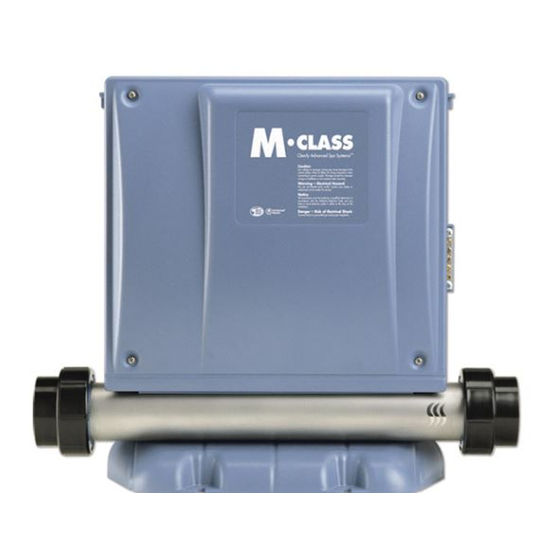
Page 13: Spa Pack's O Verall Dimensions
Specifications Spa Pack Overall Dimensions " 5/16 338 mm " 400 mm Mounting feet Heater " 108 mm " 467 mm The cover of the MC-MP-SBD power box can easily be Removable Cover removed. Simply loosen the 4 front cover screws to access connectors and jumpers. -
Page 14: Installation
Installation Overlays Please note that the following installation procedure is similar for K-8 Note and K-3 pack overlays. M ake sure to select the overlay that goes with your spa configuration. K-8 overlays K-3 overlays To properly install an overlay Installation on a keypad, you only need a hair dryer, paper towel and... - Page 15 Installation Overlays Peel the protective paper from the overlay. Gently heat the back of the overlay with the hair dryer. Heat the surface of the keypad. Place the overlay on the keypad starting with its left side. Make sure the overlay is well aligned and rests perfectly in the recess of the keypad.
- Page 16 Installation M ain Top Side Control (K-8) If the keypad is physically damaged, the spa must not be used Note and the keypad should be replaced immediately. The control keypad may be installed either with brackets or Location adhesive, directly on the spa (or very close to it) within easy reach of the user.
-
Page 17: Main Keypad (K-8)
Installation M ain Top Side Control (K-8) 1• Select the most appropriate " Bracket " 162 mm 67 mm location for the keypad. Installation 2• Cut out a 2 5/8" x 6 3/8" (67 x 162 mm) rectangular opening directly on the edge of the spa. -
Page 18: O Ptional Second Keypad (K-3)
Installation Optional Secondary Top Side Control (K-3) If the keypad is physically damaged, the spa must not be used and Note the keypad should be replaced immediately. The first step in the K-3 installation procedure is to select an Location appropriate location: the control keypad should be installed directly onto the spa (or very close to it) in order to be easily accessible to the user. -
Page 19: Power Box
Installation Power Box The MC-MP-SBD provides for versatile installation: brackets allow wall installation and special mounting foot floor installation. In both cases a special plastic guide plate facilitates installation. 1• Select most appropriate Standard floor location on floor for installation spa pack and firmly procedure attach guide plate to... - Page 20 Installation Power Box 1• Select most appropriate Standard wall location on the wall for installation spa pack and attach procedure guide plate to wall with 3 standard screws. 2• Slide bottom of pack into place by positioning it over the two brackets on top edge of guide plate.
-
Page 21: O Ptional Temperature Probe Holder
Installation Optional Temperature Probe H older " Spa Builder's temperature probe 35 mm Optional holder is designed to securely Wet-End Fitting hold a 3/8" ( ) by 2" ( 10 mm 51 mm " long temperature probe to the spa. 38 mm Select the best location to •... -
Page 22: J Umper Set-Up
Installation J umper Set-Up Your MC-MP-SBD has been factory-adjusted to be operational as soon as it is under power. However, it is possible to change some parameters of your MC-MP-SBD by repositioning specific jumpers located on the board or by setting the low level programming. - Page 23 Installation J umper Set-Up Positions JMP1: Current limiting option J umper J MP1 is used to limit the current drawn when either 2 pumps, or a pump and a blower are operating at the same time. Position 1 (HC) [*]: The heater may be turned on when both pumps are operating at high speed.
-
Page 24: Keypad & Temperature Probe
Installation M ain Keypad & T emperature Probe Loosen the four screws that secure the plastic cover of your Connecting to the spa pack’s power box and remove the cover. Power Box The main spa side keypad must be connected to the standard side panel port of the power box. -
Page 25: Connecting Your Mc-Mp-Sbd
Installation Connecting Y our M C-M P -SBD The MC-MP-SBD must be connected to your spa's Connect to Spa plumbing. Make connections to the tail pieces located on Plumbing each side of the heater tube. Connections must be perfectly sealed. Refer to your spa manual for more information on how to properly seal your plumbing connections. -
Page 26: Low Level Programming
Low Level Programming Certain system operating parameters can be configured from the keypad. This is normally done by Spa Builders or the spa installer, but may be done any time. Low level programming On/Off To access low level programming, press and hold key for 20 seconds, the first parameter's code should appear on the display. - Page 27 Notes: MC-MP -SBD O wner’s Manual...
-
Page 28: Output Connections & Set-Up
Output Connections & Set-Up Connecting Outputs The pumps, blower, ozonator and circulation pump must be Connecting connected to their respective connectors. Connectors are Equipment located on the left side of the pack for the horizontal-heater model. They are clearly identified. Your MC-MP-SBD also comes with a light socket that is ready to receive a lamp. - Page 29 Notes: MC-MP -SBD O wner’s Manual...
-
Page 30: Electrical Wiring
Electrical Wiring Electrical Service Box, GFCI & and Spa Pack • Refer to wiring diagrams supplied. • Remember: Connections must be made by a certified electrician! • W arning: Total current ouput cannot exceed total input rating! Electrical box GFCI Pack terminal block 240 VAC input supply wiring LINE 1... - Page 31 Notes: MC-MP -SBD O wner’s Manual...
-
Page 32: Operating Instructions
Operating Instructions M C-M P-SBD Operation and Functions By default, the system is On/ Off Key always on as soon as it is under power. The unit will regulate the spa tempera- ture to the desired Set Point and the display will show the current water temperature. -
Page 33: Blower Key
Operating Instructions M C-M P -SBD Operation and Functions Blower key is used to Blower Key turn the blower on or off and to select between low and high speeds. Blower Press to turn the blower on at high speed. Press a second time to "Blower"... -
Page 34: Up & Down Keys
Operating Instructions M C-M P-SBD Operation and Functions Light For spas with an optional fiber box, press the key once to Light Key turn the fiber box on (motor & light). Pressing a second time turns (Fiber Box) fiber box motor off, but leaves light on, allowing you to select color options. -
Page 35: Water Heater Automatic Start
Operating Instructions M C-M P -SBD Operation and Functions If water temperature falls Automatic Water ° ° F (0.5 C) lower than the Heater Start Set Point, the heater auto- matically turns on until the water temperature reaches ° ° Set Point plus 1 F (0.5 The "Heater"... - Page 36 Operating Instructions M C-M P-SBD Operation and Functions Filter Cycle To program filter cycle duration: (Continuation) Filter • Press key. • The display will show "Fd xx", with "xx" representing the current set filter cycle duration in hours. • Use &...
- Page 37 Operating Instructions M C-M P-SBD Operation and Functions 40-minute filter cycle time-out: Filter Cycle • If a pump, blower or light is turned on during a filter cycle, the (Continuation) cycle will be interrupted and will only be resumed 40 minutes after the last active output has been turned off.
-
Page 38: Keypad Lockout
Operating Instructions M C-M P-SBD Operation and Functions Your spa keypad can be locked. This feature is especially useful if Keypad Lockout young children have access to the keypad. To Partially lock the keypad: Pump 1 Press and hold for 5 seconds. If properly programmed, the "LO CP"... -
Page 39: Inverted Display
Operating Instructions M C-M P-SBD Operation and Functions A simple key press sequence inverts the display to make it readable Inverted Display from inside or outside the spa. To invert the display: Filter • Press and hold key for 5 sec- onds. -
Page 40: O Zonator
Operating Instructions M C-M P-SBD Features Depending on system configuration, the ozonator can be on Ozonator during the filtering cycle, always on or it may operate at the same time as the circulation pump. If a pump, blower or spa light is turned on manually, the ozonator automatically turns off and comes back on 40 minutes after last active output has been turned off. - Page 41 Notes: MC-MP -SBD O wner’s Manual...
-
Page 42: Alarm & Error Displays
Alarm & Error Displays Alarm Displays Pump starts by itself for 1 minute on several occasions and "Filter" indicator is flashing. (Also see page 39) Not a bug, but a feature! The Smart Winter Mode is protecting your spa from the cold by turning pumps on for 1 minute several times a day to prevent water in pipes from freezing. -
Page 43: Error Displays
Alarm & Error Displays Error Displays Flashing dots means the system has detected a problem with the pressure switch (water flow related error message) or the Hi-limit probe protection. 3 flashing dots are displayed: A problem has been detected. Do not enter the water! Check and open water valves. Clean filter if necessary. -
Page 44: Wiring Diagram
Wiring Diagram The wiring diagram below provides a general idea of M C-M P-SBD wiring, but it is impor- tant to note that it may not apply to all systems. The wiring diagram included on inside power box cover is the one to be used as main reference for the spa you are servicing. Pump 1 Blower Circulation Pump... - Page 45 Notes: MC-MP -SBD O wner’s Manual...
-
Page 46: Factory Default Settings
Miscellaneous Factory Default Settings J umper - J umper default setting: J MP1 = HC - Pump 1: 240 VAC output O utputs - Pump 2: 240 VAC output - O zonator: 120 VAC output - Circ. pump: 120 VAC output - Blower: 120 VAC output - Light:... - Page 47 CLEARLY ADVANCED SPA SYSTEMS! ™ For more information about our spa packs and all our other products and services, visit our web site at www.sbsg-equipment.com Smart Winter Mode 1.866.NEW.SBSG 9919-100463 3-85-7093 (1.866.639.7274)
Need help?
Do you have a question about the M-CLASS MC-MP-SBD and is the answer not in the manual?
Questions and answers