
Related Manuals for Gecko MSPA-1-AS


Summary of Contents for Gecko MSPA-1-AS
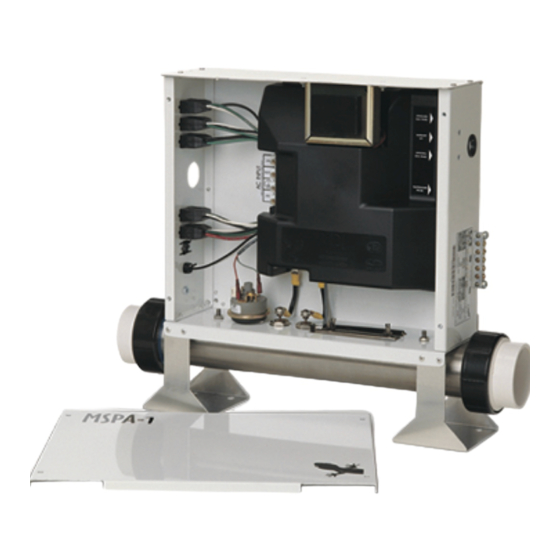
- Page 1 MSPA-1-AS Service Manual • • Visual step-by-step guide to easily identify & correct technical problems! GECKO...
-
Page 2: Table Of Contents
Contents Preliminary Required Material Power & Ground Check GFCI Electrical Wiring GFCI Trips! Programming Jumper Setup Error Messages "FLO" "FLC" "Prr" "Prh" "HL" "FrE" Troubleshooting Nothing Works! Spa Is Not Heating! Pump 1 Does Not Work! Pump 2 Does Not Work! Blower Does Not Work! Spa Light Does Not Work! Ozonator Does Not Work! - Page 3 In order to be as helpful as possible, most sections of this manual were written in two distinct formats: problem-solving solutions are described using both troubleshooting flow charts and step-by-step procedures. They should be used in conjunction, flow charts giving a global overview of specific problems while step-by-step procedures are more detailed.
-
Page 4: Preliminary
Notes: The equipment delivered may slightly differ from the illustrations shown in this manual. Gecko Electronics Inc. sells Professional Repair Kits that include everything needed for MSPA-1-AS Power Spa Pack servicing. For more information, go to the last page of this manual. - Page 5 Notes: Service manual...
-
Page 6: Power & Ground Check
GFCI starts Replace tripping. transformer. Replace the defective component. If the GFCI is still tripping, The cable Replace disconnect is defective. the GFCI. the power input wires. Call an electrician! Is the GFCI still tripping? Replace the board. MSPA-1-AS... -
Page 7: Electrical Wiring
POWER & GROUND CHECK Electrical Wiring Proper wiring of the electrical service box, GFCI and spa pack terminal block is essential. • Make a visual inspection for signs of miswiring. Refer to the supplied wiring diagram. Call an electrician if necessary. 1 x 230 VAC (32 A) input supply wiring LINE LINE 1... -
Page 8: Gfci Trips
Call an electrician! b- If the GFCI stops tripping, replace it. If the GFCI is still tripping, replace the board referring to the "How to Replace the Board" section of this manual. 4• If the GFCI still trips, replace the transformer. MSPA-1-AS... - Page 9 Notes: Service manual...
-
Page 10: Programming
It is possible to change some parameters of your MSPA-1-AS Spa Pack by positioning specific jumpers located on the board. To access the jumpers, first remove the plastic cover inside your MSPA-1-AS Spa Pack power box referring to the "How to Replace the Board" section of this manual. - Page 11 Notes: Service manual...
-
Page 12: Error Messages
Is the installation Replace the recent (less than pressure Does the "FLO" message two years)? switch cable. disappear? Adjust the Replace the Replace pressure switch. pressure switch. the board. MSPA-1-AS... - Page 13 ERROR MESSAGES "FLO" Error Message The "FLO" error message is displayed when a problem is detected with the pressure switch. The system does not detect any pressure when the pump is (whether manually or automatically) activated. Note: The heater barrel has to be installed on the pressure side of the pump and not on the suction side! For systems manufactured before 1998, the "FLO"...
- Page 14 (Refer to the respective section of this manual). Remove the plastic cover and replace the cable. 7• If the problem persists, replace the board referring to the "How to Replace the Board" section of this manual. MSPA-1-AS...
- Page 15 Notes: Service manual...
-
Page 16: Flc
Replace the recent (less than pressure 2 years)? switch cable. Replace the Adjust the pressure switch. pressure switch. Replace the board. If the "FLC" message is still displayed when you start or stop the pump, replace the pressure switch. MSPA-1-AS... - Page 17 ERROR MESSAGES "FLC" Error Message The "FLC" error message is displayed when a problem is detected with the pressure switch. The system detects pressure while the pump is not running. For systems manufactured before 1998, the "FLC" message remains displayed until any key is pressed.
-
Page 18: Prr
(a small coating of film may cause a bad connection). Reconnect the probe. Replace the probe with a spare one and verify if the problem is solved. If it is, replace the defective probe. Replace the board. MSPA-1-AS... - Page 19 ERROR MESSAGES "Prr" Error Message The "Prr" error message is displayed when a problem is detected with the temperature regulation probe: the system is constantly verifying if the sensed temperature remains within normal range. Note: For systems manufactured from 1999 onward, the "Prr" message is ignored for an hour to allow the water temperature to reach 36 ºF (2 ºC).
-
Page 20: Prh
(a small coating of film may cause a bad connection). Reconnect the sensor. Replace the sensor with a spare one and verify if the problem is solved. If it is, replace the defective sensor. Replace the board. MSPA-1-AS... - Page 21 ERROR MESSAGES "Prh" Error Message The "Prh" error message is displayed when a problem is detected with the high-limit sensor: the system is constantly verifying if the sensed temperature remains within normal range. Press a key after each step to reset the system. 3•...
- Page 22 Verify if the high-limit feel hot? look for air locks, sensor is properly closed valves or anything connected. Try to that could limit the clean the pins. Reconnect flow of water. the sensor. Replace the sensor. Replace the board. MSPA-1-AS...
- Page 23 ERROR MESSAGES "HL" Error Message The "HL" error message is displayed when a problem is detected with the high- limit sensor: the system has shut down the heater because the water temperature at the heater has reached 119 °F (48 °C). Switch the GFCI off then on between each step to reset the system! 1•...
- Page 24 5• If you do read ≈230 VAC, replace the board referring to the "How to Replace the Board" section of this manual. 3• Remove the plastic cover. Using a multimeter, measure the voltage between the two heater wires on the board. MSPA-1-AS...
- Page 25 ERROR MESSAGES "HL" Error Message If a digital thermometer reading of the water temperature is 119 °F (48 °C) or higher while the right temperature is not displayed on the top side control, perform the following: 1• Verify if the temperature probe is in contact with the water or if cold air coming from the back can affect its reading.
-
Page 26: Fre
Is the water temperature in the spa lower than the set point? Do you read ≈230 VAC to the heater ter- minals on the board? Refer to the "Spa Is Not Heating!" section. The system is working properly. MSPA-1-AS... - Page 27 ERROR MESSAGES "FrE" Error Message The "FrE" error message is related to the freeze protection of the system. (The system automatically enters the anti-freeze protection mode) Power can remain on when performing the following steps. 1• With the help of a digital thermo- meter, measure the temperature of the water.
-
Page 28: Troubleshooting
If nothing is still displayed on the top side control, replace the transformer fuse (F6). Clean the pins of the transformer orange connector using a screwdriver (a small coating of film may cause a bad connection). Replace the transformer. Replace the board. MSPA-1-AS... -
Page 29: Nothing Works
TROUBLESHOOTING Nothing Works! If the equipment is connected but nothing seems to work, the power supply must be defective. Refer to the "Power & Ground Check" section of this manual. If required, proceed as follows: 1• On the power supply terminal block, 3•... - Page 30 2• If the problem persists, replace the transformer fuse (F6). 4• If the system still does not work, replace the transformer. 5• If the problem is not solved yet, replace the board referring to the "How to Replace the Board" section of this manual. MSPA-1-AS...
- Page 31 Notes: Service manual...
- Page 32 Are the heater wires Replace the properly connected temperature probe. both to the board and to the element? Replace the board. Tighten the heater wires both to the board and to the element. Is the problem solved? Replace the heater. MSPA-1-AS...
-
Page 33: Spa Is Not Heating
TROUBLESHOOTING Spa Is Not Heating! If the system does not seem to be heating the water, proceed as follows: 1• Verify if an error message is displayed If the "Heater" marker does not appear: on the top side control. If so, refer to the message specific section of this manual. - Page 34 If you do not read ≈230 VAC, replace the board. If necessary, tighten the two wires both to the heating element and to the board. 3• If the problem still persists, replace the heater referring to the "How to Replace the Heater" section of this manual. MSPA-1-AS...
- Page 35 Notes: Service manual...
- Page 36 Replace the pump 1 or pump 2 fuse. Does the problem persist? Measure the voltage for both speeds. Do you read ≈230 VAC for both speeds to the pump terminals Replace pump 1 Replace on the board? or pump 2. the board. MSPA-1-AS...
-
Page 37: Pump 1 Does Not Work
TROUBLESHOOTING Pump 1 Does Not Work! If pump 1 does not work, proceed as follows: To increase the lifetime of the relay, a circuit called "snubber" is used on the pump relay. With this type of circuit, if no pump is connected to an output and the relays are open, the multimeter will still read voltage of around 60 V. - Page 38 Turn pump 1 to high speed and measure the voltage between the pump terminals (P15 & P22 on the board). You should read ≈230 VAC. Note: If necessary, refer to the supplied wiring diagram! MSPA-1-AS...
-
Page 39: Pump 2 Does Not Work
TROUBLESHOOTING Pump 2 Does Not Work! If pump 2 does not work, proceed as follows: To increase the lifetime of the relay, a circuit called "snubber" is used on the pump relay. With this type of circuit, if no pump is connected to an output and the relays are open, the multimeter will still read voltage of around 60 V. - Page 40 Turn pump 2 to high speed and measure the voltage between the pump terminals (P13 & P24 on the board). You should read ≈230 VAC. Note: If necessary, refer to the supplied wiring diagram! MSPA-1-AS...
- Page 41 Notes: Service manual...
- Page 42 It may be that the Replace blower does not Replace have enough blower. air entry. blower fuse (F7). Create an opening to let more air reach the blower. Replace the board. MSPA-1-AS...
-
Page 43: Blower Does Not Work
TROUBLESHOOTING Blower Does Not Work! If the blower does not work, proceed as follows: To increase the lifetime of the relay, a circuit called "snubber" is used on the blower relay. With this type of circuit, if no blower is connected to an output and the relays are open, the multimeter will still read voltage of around 60 V. - Page 44 If the blower does not restart after cooling down, replace it. 5• If the blower does restart after cooling down, it may be that the blower does not draw enough air. 6• If so, create a bigger opening to let more air reach the blower. MSPA-1-AS...
- Page 45 Notes: Service manual...
- Page 46 Replace the board. Do you read ≈12 VAC to the light terminals on the board Replace Replace when the light is the spa the spa light at high intensity light socket. fuse (F1). (marker non-blinking)? Replace the board. MSPA-1-AS...
-
Page 47: Spa Light Does Not Work
TROUBLESHOOTING Spa Light Does Not Work! If the spa light does not work, proceed as follows: It is important to measure voltage when the spa light is powered on! 1• Verify the spa light bulb and replace it if necessary. "Light"... - Page 48 Cycle" marker displayed when you press Do you read Start a filter cycle. the respective ≈230 VAC to The respective marker key? the ozonator should be displayed. terminals on the board? Replace Replace ozonator. ozonator fuse (F3). Replace the board. MSPA-1-AS...
-
Page 49: Ozonator Does Not Work
TROUBLESHOOTING Ozonator Does Not Work! If the ozonator does not work, proceed as follows: To increase the lifetime of the relay, a circuit called "snubber" is used on the ozonator relay. With this type of circuit, if no ozonator is connected to an output and the relays are open, the multimeter will still read voltage of around 60 V. - Page 50 If one of the keys does not work, follow the troubleshooting flow chart below to identify the source of the problem. Verify jumper settings. Replace the top side control by a spare one. Are the keys working? Replace the defective Replace top side control. the board. MSPA-1-AS...
-
Page 51: Keys Do Not Work
TROUBLESHOOTING Keys Do Not Work! If one of the keys on the top side control does not work, proceed as follows: Jumper location 1• Verify if the jumpers are properly set referring to the respective section of this manual. 2• Replace the top side control by a spare one. -
Page 52: How To
(located to the left of the board). 4• Gently remove the plastic cover by releasing its upper part first. 2• Disconnect the top side control(s) and the temperature probe (connectors located in the upper right corner of the board). MSPA-1-AS... - Page 53 HOW TO Replace the Board 5• Disconnect the transformer. 7• Disconnect all outputs (pumps, spa light, ozonator) using a pair of pliers. Make sure not to damage the connectors! 8• Disconnect the high-limit sensor 6• Using a nut driver, remove the and the pressure switch.
- Page 54 10• Loosen the two triac screws 12• Gently remove the board by while holding them with a pair of releasing its left part first. pliers to prevent damage, then remove the ground screw. * On models manufactured before 1999, loosen the 6 screws. MSPA-1-AS...
- Page 55 HOW TO Replace the Board 13• Verify if the plastic standoffs are 18• Reconnect the heater. damaged. If they are, replace them. 19• Reconnect the high-limit sensor 14• Align the new board with the plastic and the pressure switch. standoffs and snap it into place. 20•...
-
Page 56: Replace The Heater
1• Disconnect the two wires at the top 2• Loosen the two wing nuts that hold of the pressure switch, then unscrew the plate of the high-limit sensor and and remove the switch. remove the sensor. MSPA-1-AS... - Page 57 HOW TO Replace the Heater 5• Slide the new heater into place and fix it to the power box using the two nuts. The two heater-fixing nuts must be properly tightened because they also serve as a current collector in case of heater failure.
-
Page 58: Adjust The Pressure Switch
6• Run the pump at low speed for 30 seconds. You should not see an "FLO" message. 7• If you see an "FLO" or an "FLC" message, repeat the procedure above. If you are not able to adjust the pressure switch, replace it. MSPA-1-AS... - Page 59 Notes: Service manual...
-
Page 60: Miscellaneous
430AE0027-P10 Fuses for pump 2 (package of 10) 56.57 76.97 * EQGX155 Main board for: MSPA-2-P122-02-LS-H5.5-JJM 225.00 306.12 * MSPA-2-P122-01-LS-H5.5-JJM 225.00 306.12 * MSPA-2-P122-01-LA-H5.5-JJM 225.00 306.12 * MSPA-2-P122-01-LS-JJM 225.00 306.12 * MSPA-2-P121-01-LS-JJM 225.00 306.12 * MSPA-2-P122-02-LS-JJM 225.00 306.12 * MSPA-1-AS... - Page 61 MISCELLANEOUS Parts List We recommend that field service technicians keep the items marked with an asterisk (*) in stock. Ref.: Part Number Description Retail U.S. EQGX196 Main board for: MSPA-1-P122-B2-01-CP2-LS-HV-JJM-NF-AX 288.97 393.15 * EQGX157 Main board for: MSPA-1-P122-P222-B1-01-LS-H5.5-JJM 302.51 411.58 * MSPA-1-P122-P222-B1-01-LS-H5.5-AMP 302.51 411.58 *...
-
Page 62: Wiring Diagram
Pump 2 Ozonator Heater Voltage 240 V Voltage 240 V Line 1 Neutral Green / Ground Green / Ground Green / Ground Ground Brown / Line Brown / Line Blue / Neutral Blue / Neutral Jumper Settings See respective section MSPA-1-AS... -
Page 63: Professional Repair Kit
Professional Repair Kit All you need in a single case! Gecko's professional repair kit contains all you need to properly service and repair Gecko's line of power spa packs. • Top side controls • Temperature probes • Pressure switch cables •...
Need help?
Do you have a question about the MSPA-1-AS and is the answer not in the manual?
Questions and answers