
Related Manuals for ePropulsion Navy 6.0T-S


Summary of Contents for ePropulsion Navy 6.0T-S
- Page 1 NAVY 6.0 USER MANUAL November, 2016 Version 1.1 Copyright © 2014-2016 ePropulsion All Rights Reserved...
-
Page 3: Acknowledgement
By using this product, you hereby agree that you have fully read and understood all contents of this manual. ePropulsion accepts no liability for any damage or injury caused by operations that contradict this manual. -
Page 4: Product Identification
Product Identification Below picture indicates the position of serial number. Please record the serial number for access to maintenance or other after-sale services. Figure 0-1... -
Page 5: Table Of Contents
Table of Contents Acknowledgement...................1 Using This Manual................1 Symbols.....................1 Product Identification................2 Table of Contents..................3 1 Product Overview................5 1.1 In the Package (R/T)................5 1.2 Parts and Diagrams................8 1.3 Specification..................9 1.4 Important Notes................10 1.5 Declaration.................11 2 Preparations..................12 2.1 Selecting the Battery..............12 2.2 Selecting and Mounting the Propeller..........13 3 Mounting the Outboard Motor............14 3.1 Position of Mounting................14 3.2 Mounting the Outboard................15... - Page 6 5.5 Pairing Remote Controller/Tiller Handle with Outboard Motor...30 5.6 Warning Messages................33 6 Configurations..................36 6.1 Preference Settings................36 6.2 Battery Configuration..............36 7 Checklist before Use................39 8 Starting the Outboard................40 9 Stopping the Outboard...............41 10 Trim Angle Adjusting..............42 11 Maintenance................44 11.1 Notes..................44 11.2 Maintenance Time Table..............44 11.3 Changing Gear Oil................45 11.4 Replenishing Coolant...............45 11.5 Propeller Maintenance..............47...
-
Page 7: Product Overview
1 Product Overview Navy 6.0 is a 6KW electric outboard motor by either remote control or tiller control. Below table shows different models of Navy 6.0. Model Control Shaft length Navy 6.0T-S Tiller 650mm/25.6" Navy 6.0T-L Tiller 775mm/30.5" Navy 6.0R-S Remote 650mm/25.6"... - Page 8 Items Qty./Unit Figure Propeller and 1 set Accessories Wrench Set 1 set Kill Switch 2 pieces Battery Bridging 3 pieces Cable Main Switch 1 piece Cable Link Arm (R) 1 set User Manual Warranty 1 set Warranty Claim Card Remote Controller 1 set...
- Page 9 Other accessories are also required to operate the outboard motor, such as the battery, charger and communication cable, etc. Users can buy official accessories provided by ePropulsion such as Navy Battery, Navy Charger and communication cable, etc. from ePropulsion authorized dealers.
-
Page 10: Parts And Diagrams
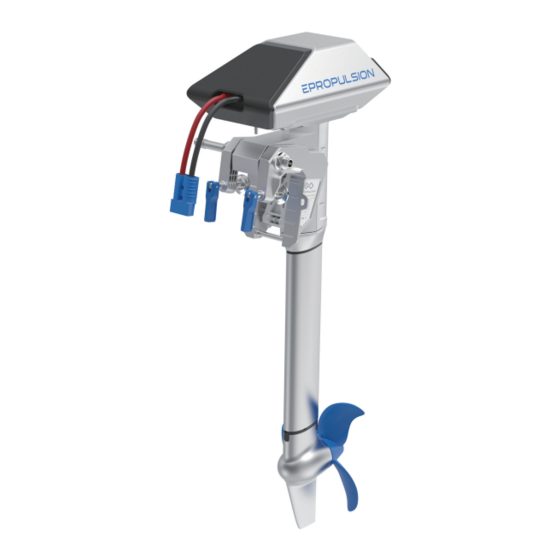
1.2 Structure and Components Motor Case GPS Module(built-in) Power Cable Steering Connector Mount Position Tube of Link Arm Release Button Bracket Clamp Trim Lever Communication Port Tightening Handle for Clamp Shaft Propeller Anode Gear Box Figure 1-1 Outboard Main Part Throttle Handle Display Screen Buttons... -
Page 11: Specification
1.3 Specification NAVY 6.0 (T / R) Type Electric Rated Voltage / Current 48V / 125A Input Voltage Range 39V ~ 60V DC Maximum Input Power 6KW / 2KW (Forward / Reverse) Comparable Petrol Outboard 9.9HP Maximum Overall Efficiency Rated Rotation Speed (Forward) 1550rpm Control System Remote / Tiller... -
Page 12: Important Notes
17. Users are responsible to assemble the propeller and steering wheel. If other assembly or disassembly is required, please contact your dealer. ePropulsion accepts no liability for any damage or malfunction caused by operations that violate this manual. -
Page 13: Declaration
The original certificate was issued by Global-Standard Testing Service Co., Ltd. in Shenzhen, Guangdong. Certificate NO.: GST140470225E; GST1404170225M; GST1404170225S; GST1404170225S. Issued Date: May 21st, 2014 Signature: Mr. Danny Tao, Chief Executive Officer & Cofounder of ePropulsion Innovation (HK) Ltd. -
Page 14: Preparations
In addition, the type and tonnage of boats also play important roles. Users can choose Navy Battery designed by ePropulsion for Navy outboard motors, which is a type of Lithium-ion battery with 3000Wh capacity. When using with Navy 6.0, two or more sets of Navy Battery are required in parallel. -
Page 15: Selecting And Mounting The Propeller
When using Navy Batteries, the batteries will work well once being correctly connected. When using non-ePropulsion batteries, before starting the outboard, users should configure the batteries via the Remote Controller for the first time use, otherwise the batteries may not work properly. -
Page 16: Mounting The Outboard Motor
3 Mounting the Outboard Motor Select an outboard with proper shaft length according to the transom height of your boat. The top of the propeller should be 100mm to 150mm below the bottom of the boat. The outboard should be mounted on the centerline of your boat. If the boat shape is asymmetric, please consult your dealer for proper solution. -
Page 17: Mounting The Outboard
3.2 Mounting the Outboard Method 1 Rotate the two clamps in clockwise direction to fix the outboard onto transom. Lock Figure 3-2 Figure 3-3 Method 2 Use two screws to fix the outboard to the boat. The dimensions of the two mounting Wholes are shown below. -
Page 18: Mounting The Steering System For Navy 6.0R
3.3 Mounting the Steering System (R) When use a Remote Controller, please prepare a steering wheel (not supplied with Navy 6.0) and mount it on the corresponding position to control the direction. Step2: Mount the Link arm with two M8 nuts. Step1: Insert the steering Step3: Fasten the steering wheel wheel shaft into the... - Page 19 Release Button Figure 3-7...
-
Page 20: Connecting The Battery
4 Connecting the Battery 4.1 Connecting a 48V Battery When using a battery, make sure the main switch is off before connection. ① First connect the main switch cables to the battery. ② Connect the main switch cables with the power cables from the outboard. ②... -
Page 21: Connecting A Navy Battery
contact. If this problem is discovered, open the back cover of the switch, and tighten the screws inside. 4.2 Connecting a Navy Battery When using a Navy Battery, make sure the main switch is off before connection. ① First connect the main switch cables to the Navy Battery. ②... -
Page 22: Batteries In Series/Parallel
Clockwisely rotate the main switch to power on the battery before use. Users can also enlarge the battery capacity by connecting multiple batteries in parallel. The main switch and the power cable are connected by the fixing screws that may loosen after long-time use. Loosen screws will lead to poor contact. -
Page 23: Remote Controller/Tiller Handle
5 Remote Controller / Tiller Handle The Remote Controller/Tiller Handle is used for starting and stopping the Navy outboard motor, adjusting the speed of the motor, configuring the battery parameters, displaying the system information and messages, etc. The Remote Controller/Tiller Handle is powered by either solar power or the built-in lithium battery. - Page 24 Buttons Functions 1. On setting pages, press " " button to save the current settings and switch to the next item. 2. On setting pages, long press the “ ” button, the system will save your settings, the display will exit from “OK”...
- Page 25 2. On preference setting page, Press “ ” button and hold to enter the battery setting page. Battery setting page If users enter the page without setting any parameters, the current parameters displayed on the page will be saved as user parameters by default.
- Page 26 Icons Functions Hidden: system temperature is in normal range. Blink: system temperature is a little high and the maximum input power of motor has been lowered than 6KW. Over-heat alert Shown constantly: system is over temperature and the outboard will stop working.
-
Page 27: Charging
Icon Function Displaying real time input power to the system. Throttle Power A blinking “RESET” indicating the throttle should be reset to zero position. 5.2 Charging Both the Remote Controller and Tiller Handle have a built-in lithium battery for power supply. The battery will be charged automatically under normal use: get charged by solar power or wired connection. - Page 28 Figure 5-4 Please follow the below steps to charge the Remote Controller/Tiller Handle by wired connection. First, connect the Remote Controller/Tiller Handle to the outboard motor by a communication cable first (Figure 5-5/Figure 5-6); Then, connect the outboard motor to the battery. Communication Cable Figure 5-5 Communication Cable...
-
Page 29: Power Adjusting
During long-term storage, ensure to charge the Remote Controller battery every 6 months to avoid over-discharge. After long-term storage, charge the Remote Controller before use. The communication cable is not included in this package. Please purchase one from your dealer if you choose this charging method. The charging process will stop once the communication cable disconnects. -
Page 30: Recalibration
Handle to start the outboard, then turn the throttle gradually form zero position to the forward direction to start. Please refer to Figure 5-8. Change the heading direction by turning the tiller on horizontal level. The maximum forward power is 6KW and the maximum backward power is 2KW. Forward Backward Zero Position... - Page 31 Recalibration process LCD Displaying Step1: Long press the “ ” button (>10secs) until “CAL FO” displays. Step2: Push the throttle to the maximum forward power position, then press“ ” button. “CAL ST” will display and “CAL” is blinking. Step3: Pull the throttle to the middle (zero) position where you can hear a click sound, then press “...
-
Page 32: Use Of Kill Switch
5.4 Use of Kill Switch Attach the lanyard of kill switch to your wrist or life jacket. Stop the outboard by detaching the kill switch in case of emergency. Figure 5-10 Figure 5-11 The kill switch generates magnetic field. Keep it 50cm / 20inches away from pacemakers and other medical implants. - Page 33 Figure 5-12 However, if the Remote Controller/Tiller Handle or the outboard motor is not replaced, but the main page of the LCD panel on the Remote Controller still displays like this, you should check and: 1) Make sure the Remote Controller is not far from the outboard motor; 2) Make sure all the equipment involved is normally powered on.
- Page 34 Step2: Long press the “ ” button until entering the pairing page (i.e. address setting page, Figure 5-14) of the Remote Controller/Tiller Handle. Meanwhile, ensure power supply of the outboard motor is normal. On this page, “ADD SET” refers to address setting, “0100607” indicates the pairing code.
-
Page 35: Warning Messages
Main Switch Main Switch Figure 5-15 Figure 5-16 5.6 Warning Messages When the outboard motor is running in abnormal conditions or out of order, a warning message with an error code will display on the LCD screen. Figure 5-17 is an example. Please find more error codes and corresponding solutions in the below table. - Page 36 Codes Causes Solutions The battery voltage R e p l a c e a b a t t e r y b a s e d o n exceeds the operating suggested operation specifications. range. Propeller may be blocked, causing motor Please refer to the solution to E10.
- Page 37 Please refer to section 5.4 Pairing characters Remote Controller/Tiller Handle with Device addresses the Outboard Motor and pair the displaying mismatch. Remote Controller/Tiller Handle with the outboard motor again. If the problem persists, please consult your ePropulsion authorized dealer for assistance.
-
Page 38: Configurations
6.2 Battery Configuration Accurate battery configuration helps achieve precise estimation of the battery's discharging state. When using an ePropulsion Navy Battery (standard), battery configuration is self-acted by the control system given that all the communication cables are well connected. When not using... - Page 39 Battery Configuration Process LCD Displaying Step1: First, turn on the main switch and the Remote Controller/Tiller Handle. Then, long press the “ ” button to enter the preference setting page. Next, long press the “ ” button again until entering the battery setting page. Users can see the voltage value blinking and it’s ready for configuration.
- Page 40 Update the battery configuration is necessary if a different type of battery has been applied. When using non-ePropulsion batteries, before starting the outboard, users should configure the batteries via the Remote Controller for the first time use, otherwise the batteries may not work properly.
-
Page 41: Checklist Before Use
7 Checklist before Use 1. Ensure the propeller is correctly and firmly mounted on the outboard. 2. Ensure the outboard is correctly and firmly mounted on the boat. 3. Ensure the throttle and steering wheel are installed in proper position bef- ore turning on the power. -
Page 42: Starting The Outboard
8 Starting the Outboard 1. Complete the check list. 2. Remove the kill switch from the Remote Controller/Tiller Handle. 3. Push/Turn the throttle to zero position. 4. Connect the battery to the outboard. 5. Fix the outboard with a proper trim angle. 6. -
Page 43: Stopping The Outboard
9 Stopping the Outboard Usually, it’s recommended to stop the outboard as the following procedures. 1. Return the throttle to zero position. 2. Wait until the outboard stops, then detach the kill switch from the Remote Controller/Tiller Handle. 3. Press and hold the “ ”button until the Remote Controller/Tiller Handle is powered off. -
Page 44: Trim Angle Adjusting
10 Trim Angle Adjusting Only adjust the outboard trim angle when the outboard is stationary. There are five trim angle options including 60°,15°,10°,5° and 0°. Adjust the outboard trim angle based on specific conditions. E.g. when the boat is in shallow water or the outboard is not in use, tilt the outboard and adjust the trim angle to 60°. - Page 45 Tilting Down The release button is raised when the trim angle is maximum at 60° position. Press the release button and tilt up the propeller shaft slightly to about 80° position, then lay it down, and the outboard shaft will return to 0° position. It’s suggested to test with different trim angles to find the optimal trim angle for the boat and operation.
-
Page 46: Maintenance
Disconnect the battery with the outboard before maintenance. Conduct the maintenance work according to the instructions from ePropulsion authorized dealers. Only use ePropulsion original components for replacement and maintenance. 11.2 Maintenance Time Table Regular maintenance helps to keep the outboard in its optimal operating state. -
Page 47: Changing Gear Oil
11.3 Changing Gear Oil In order to reduce gear wear, regular gear oil replacement is necessary. It’s suggested to contact your dealer for the oil change. The oils like GL-4 and SAE 90 are recommended. Conduct the oil change operations as the steps below. - Page 48 1.Use a M6 Allen wrench to screw out four screws fixing the motor case. Motor Top Case Coolant Tank Motor Bottom Case M6 Allen Screws Figure 11-2 2. Check the coolant tank. If it’s not filled, pull the flange out of the injection hole on the coolant tank, then replenish the coolant tank with the liquid mixture of the recommended ANT coolant and water at a mix ratio of 7 to 3.
-
Page 49: Propeller Maintenance
11.5 Propeller Maintenance Disconnect the battery with outboard before maintenance. Gloves are recommended to protect your hand from sharp propeller edges. Check the propeller according to the following instructions, then refer to then refer to section 2.3 Propeller Assembly to replace a new propeller if necessary. -
Page 50: Transportation And Storage
12 Transportation and Storage 12.1 Transport For long distance transport, please use the ePropulsion original packing materials to pack the outboard before delivery. Figure 12-1 12.2 Placement When placing the outboard on a surface, ensure the surface is flat and horizontal. -
Page 51: Emergency Situations
13 Emergency Situations 13.1 Collision If the outboard strikes some object beneath the water, please follow below procedures. 1. Stop the outboard immediately and then turn off the main switch. 2. Check the mechanical structure to see if there are damages. 3. -
Page 52: Warranty Claims
14 Warranty Claims The ePropulsion limited warranty is provided for the first end purchaser of an ePropulsion product. Consumers are entitled to a free repair or replacement of defective parts or parts which do not conform with the sales contract. -
Page 53: Out Of Warranty
Warranty Claim Card, ex-factory serial number, and evidence of purchase. 2. Send the defective product to your authorized ePropulsion service point after getting the confirmation. Note that the label should be kept intact. - Page 54 3. The defective components or parts will be either repaired or replaced according to the diagnosis made by the ePropulsion authorized service partner. 4. If your warranty claim is accepted, the equipment will be repaired or replaced free of charge. Note that any delivery cost incurred in the process is at your charge.
- Page 56 Thanks for reading this user manual. If you have any concerns or find any problems while reading, please don't hesitate to contact us. We are delighted to offer service for you. ePropulsion Innovation (HK) Ltd. Website: www.epropulsion.com Email: service@epropulsion.com...
Need help?
Do you have a question about the Navy 6.0T-S and is the answer not in the manual?
Questions and answers