
Related Manuals for ePropulsion POD DRIVE EVO


Summary of Contents for ePropulsion POD DRIVE EVO
- Page 1 POD DRIVE EVO USER MANUAL Pod Drive 1.0 / Pod Drive 3.0 / Pod Drive 6.0 Jan, 2021 Version 1.0 Copyright © 2021 ePropulsion. All Rights Reserved...
-
Page 3: Acknowledgement
Before use of the product, please read this user manual thoroughly to understand the correct and safe operations. By using this product, you hereby agree that you have fully read and understood all contents of this manual. ePropulsion accepts no liability for any damage or injury caused by operations that contradict this manual. -
Page 4: Product Identification
Product Identification Below picture indicates the serial numbers of Pod Drive Evo. Please note the position of the serial numbers and record them for access to warranty service and other af- ter-sale services. Figure 0-1 Electric Pod Drive Model: Pod Drive 3.0 Evo... -
Page 5: Table Of Contents
Table of Contents Acknowledgement ..................1 Using This Manual ..................1 Symbols ....................1 Product Identification ................2 1 Product Overview ................... 5 1.1 In the Package ..................5 1.2 Parts and Diagrams ................. 8 1.3 Technical Data ..................10 1.4 Declaration of Conformity .............. - Page 6 6 Checklist before Use ................35 7 Starting the Pod..................35 8 Stopping the Pod .................. 36 9 Hydro generation function ..............37 10 Maintenance ..................38 10.1 Propeller Maintenance ................ 38 10.2 Replacing the Anode ................38 11 Transport and Storage ................ 40 12 Emergency Situations .................
-
Page 7: Product Overview
1.1 In the Package When you receive a set of Pod Drive Evo, unpack its package and check if all the items below are included in the package. If there is any loss or transport damage, please contact your dealer immediately. - Page 8 Spirit Battery Plus Pod Drive 3.0 Evo & Pod Drive 6.0 Evo Pod Motor 1 Set Driver Module 1 Set Wrench Set 1 Set Main Switch Cable 1 Set Shared by Pod Drive Evo Evo Remote Control 1 Set (Purchased separately)
- Page 9 The Evo Remote Control need to be purchased separately. Other accessories such as batteries, charger, etc. appearing in this manual but not included in this package list require users to purchase them from ePropul- sion authorized dealers. Save ePropulsion original package for transport and storage.
-
Page 10: Parts And Diagrams
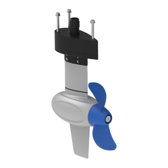
1.2 Parts and Diagrams Communication module Communication cable Power cable Main switch Product label Corrugated pipe M8 screw M8 washer M8 bolt Adjusting pad Supporting tube Motor Anode Propeller Skeg Figure 1-1 Pod Drive 1.0 Evo Power cable connector Dust cover Power cable Product label Heat sink... - Page 11 Temperature line Corrugated pipe Phase line icon Three-phase line M8 locknut M8 bolt M8 washer Adjusting pad Supporting tube Propeller Motor Anode Skeg Figure 1-3 Pod Drive 3.0 Evo Temperature line Corrugated pipe Phase line icon Three-phase line Supporting tube M10 locknut M10 bolt M10 washer...
-
Page 12: Technical Data
Figure 1-4 Pod Drive 6.0 Evo 1.3 Technical Data Pod Drive 1.0 Pod Drive 3.0 Pod Drive 6.0 Type Electric Rated Voltage Rated Current 20.8 A 62.5 A 125 A Comparable Petrol Outboard 3 HP 6 HP 9.9 HP Maximum Overall Efficiency Rated Rotation Speed 1200 rpm 2300 rpm... -
Page 13: Declaration Of Conformity
Object of the Declaration: Product: Electric Outboard Motor Model: Pod Drive 1.0 Evo, Pod Drive 3.0 Evo, Pod Drive 6.0 Evo Company Name: Guangdong ePropulsion Technology Limited Address: Room 201, Bldg.17A, 4th XinZhu Road, SongShan Lake District, Dongguan City, Guangdong Province, China... -
Page 14: Important Notes
2. Only adults who have fully read and understood this manual are allowed to operate this product. Read the full user manual carefully before operation, ePropulsion accepts no liability for any damage or malfunction caused by operations violating this manual. 3. Only boat owners who are familiar with their boats are allowed to use this pod system. -
Page 15: Checking The Propeller
2 Checking the Propeller Before use, check the propeller and if necessary, eg. the original propeller is broken, change a new propeller. Follow instructions in Figure 2-1~2-3 to assemble a propeller properly. Assemble a propeller for Pod Drive1.0 Evo: Step1: Attach the washer. Step2: Fix the pin to the hole on motor shaft. - Page 16 Assemble a propeller for Pod Drive3.0 Evo: Step1: Attach the Φ12 washer. Step2: Fix the pin to the hole of shaft. Step3: Attach the propeller. Step4: Attach the Φ12 washer. Step5: Tighten the nut with 19mm (3/4 inch) socket wrench. Step6: Attach the Anode.
-
Page 17: Mounting The Motor
3 Mounting the Motor Step 1: Drill four holes in the proper position through the hull bottom. The suggested dimensions of the four holes are shown below (please refer to the fixing guide ) : Pod Drive1.0 Evo: 3xφ9mm φ37mm 52mm 85mm Figure 3-1... - Page 18 Step 2: Hold the pod motor and insert its three bolts (Pod Drive 1.0 & 3.0 are M8, Pod Drive 6.0 Evo is M10) and supporting tube into the holes from below the hull bottom. Then lock the each bolt from inside the boat by a plain washer and a nut (Figure 3-4). Supporting Tube Locknuts Plain washers...
- Page 19 Pod Drive 3.0 & 6.0 Evo: Step 3: Check the three phase lines U-U1, V-V1, W-W1, put the three phase lines into the phase line clamp; fix the terminal on the driver with the hexagon screw M10 and washer (tightening torque 8 -10Nm); finally insert the temperature line into the corre- sponding connector and tighten it.
- Page 20 8.40mm 8.40mm 290mm Figure 3-8...
-
Page 21: Connecting The Battery
Before connecting to a battery, make sure the main switch is off, and fix the battery and communication module/driver on the boat. 1. Connect the power cable of the pod drive to the battery. 2. If use ePropulsion batteries, please connect the battery and pod drive with a communication cable. Main... -
Page 22: Connecting A Spirit Battery Plus (Only For Pod Drive 1.0 Evo)
4.2 Connecting a SPIRIT Battery Plus (Only for Pod Drive 1.0 Evo) If you use the Pod Drive 1.0 Evo and SPIRIT Battery Plus at the same time, please fol- low the steps below to connect SPIRIT Battery Plus and the communication module of Pod Drive 1.0 Evo: 1. Before connecting the battery and communication module, please fix the battery and communication module on the boat. -
Page 23: Evo Remote Control
5 Evo Remote Control 5.1 Display Panel GPS Status Indicator Reverse charging indicator Wireless Connecting Indicator Overheat Alert Kill Switch Status Indicator Safety Wristband Status Battery Level Indicator Indicator Number of Safety Wristband Battery Level / Voltage Motor Fan Fault Current Speed Travelled Distance / Time or Remaining Distance / Time... - Page 24 Buttons Functions 1. On any setting page, press " " button to view options for current setting. 2. In power-on state, when home page displays, press " " button and hold 10s to enter the throttle calibration page. 3. On home page, press " "...
- Page 25 If users enter the page without setting any parameters, the current parameters displayed on the page will be saved as user parameters by default. Icons Functions Battery level Indicating approximate battery level. The solid blocks stand for remaining battery. indicator Indicating accurate current battery level percen- tage/battery voltage, is configurable in preferen- ce setting page.
- Page 26 Icons Functions Blink:The motor fan has faults. Please con- Motor fan fault tact the dealer to check the fan wiring. Displaying real time travel distance/time. Set Distance/time units (MILE, KM (kilometer) and NM (nautical mile)) in preference setting page. display The time unit is HR (hour).
-
Page 27: Charging
5.2 Charging The remote control has an in-built lithium battery for power supply. The battery will be charged automatically under normal use: get charged by solar power or wired con- nection. 5.2.1 Charging by Solar Power When the solar panel receives enough sunshine, it will generate electricity to charge the in-built lithium battery. - Page 28 In this case, charging by wired connection is faster. Use a communication cable to connect the remote control and the communication module/driver. Then make sure the system battery is well connected to the pod drive and powered on. Battery Communication cable Figure 5-4 During long-term storage, ensure to charge the remote control every 6 months to avoid over-discharge.
-
Page 29: Power Adjusting
5.3 Power Adjusting 5.3.1 Power Adjusting for Evo Remote Control Please place the kill switch on the Evo remote control before operation. The Evo Remote Control is mainly used to adjust the input power of the motor. When the battery is well connected and switched on, power on the Remote Control to start the pod drive, then slowly push the throttle forward position to increase the power. -
Page 30: Recalibration
5.3.2 Recalibration If the error code displays as the figure 5-6, users should calibrate the throttle strictly as below steps. Figure 5-6 Recalibration process LCD Displaying Step1: Long press “ ” button for 10s until “CAL FO” displays. Step2: Push the throttle to the maximum forward power position, then press "... -
Page 31: Use Of Kill Switch
Recalibration process LCD Displaying Step5: Push the throttle to zero position and press the “ ” button and return to the main page. 5.4 Use of Kill Switch • Attach the kill switch and tie its lanyard to your wrist or life jacket. • Stop the pod drive in emergency by detaching the kill switch. -
Page 32: Use Of Safety Wristband
5.5 Use of Safety Wristband 5.5.1 Pairing safety wristband with remote control Press the " " and " " buttons and hold for a while to display the safety wristband icon and “SE”. At this time, approach the safety wristband that needs to be paired, turn on the safety wristband, and the remote control displays the “SUC”, indicating successful pairing. -
Page 33: Pairing Remote Control With The Pod Drive
When a wristband is disconnected or an emergency stop is performed, the stop command of other wristbands will not work until it returns to the normal state. 5.6 Pairing Remote Control with the Pod Drive Before use please pair remote control with the pod drive. There are two methods to pair the remote control. - Page 34 Method 2. Pairing with Communication Cable Step1: Switch off system power and the remote control. Step2: Connect the remote control and the Communication module with a communi- cation cable. Step3: Switch on system power and the remote control. Wait for them to get paired in seconds.
-
Page 35: Warning Messages
5.7 Warning Messages When the pod drive motor is running in abnormal conditions or out of order, a warning message with an error code will display on the LCD panel. Figure 5-12 is an example. Please find more error codes and corresponding solutions in the below table. Figure 5-12 Code Cause... - Page 36 Connect the battery to the pod drive All cha- and then turn on the main switch. racters Pairing Re- Please refer to section 5.6 display Not paired mote Control with the Pod Drive. If the problem persists, please consult your ePropulsion authorized dealer for assistance.
-
Page 37: Checklist Before Use
2. Remove the kill switch from the remote control. 3. Push the throttle to zero position. 4. Connect the battery with the pod drive. 5. If use ePropulsion battery, turn on the main switch. 6. Press “ ” button to turn on the remote control. -
Page 38: Stopping The Pod
8 Stopping the Pod Drive It’s recommended to stop the pod drive as the following procedures. 1. Return the throttle to zero position. 2. Wait until the motor stops, then detach the kill switch. 3. Press and hold the “ ” button until the remote control is switched off. 4. Turn off the main switch. -
Page 39: Hydro Generation Function
9 Hydro Generation Function Pod Drive Evo machines can drive the propeller to charge the battery (only the ePropulsion battery) through water flow. The machine will enter the hydro generation state if the following conditions are met: 1. The remote control is set to turn on the hydro generation function (enabled by default). -
Page 40: Maintenance
10 Maintenance 10.1 Propeller Maintenance Ensure the battery is disconnected before each check, as a rotating propeller is dangerous. Gloves are recommended to wear, in order to protect your hand from the sharp propeller edges. Check the propeller based on the following tips, then refer to the Chapter 2 Checking the Propeller to replace a new propeller if necessary. - Page 41 Anode Figure 10-2 Replace Pod Drive6.0 Evo anode...
-
Page 42: Transport And Storage
11 Transport and Storage Before long distance transport or long-term storage, please use ePropulsion original package to pack the pod drive. Figure 11-1 Make sure the pod drive gets adequate damping protection before transport and storage. Store the pod drive in a well-ventilated and dry area without direct sun exposure. -
Page 43: Emergency Situations
12 Emergency Situations 12.1 Collision If the pod strikes some object beneath the water, please follow below procedures. 1. Stop the pod immediately and then turn off the main switch. 2. Check the mechanical structure to see if there are damages. 3. Return to the nearest harbor or pier in low power. 4. Call your dealer to check the pod. -
Page 44: Warranty
13 Warranty The ePropulsion limited warranty is provided for the first end purchaser of an ePro- pulsion product. Consumers are entitled to a free repair or replacement of defective parts or parts which do not conform with the sales contract. This warranty operates in addition to your statutory rights under your local consumer law. -
Page 45: Out Of Warranty
Free warranty is not transferable and will not be reissued. 13.2 Out of Warranty Make sure the product is properly packed during delivery, the original ePropulsion package is recommended. If the product get further damage due to improper packing during delivery, the furtherly damaged part will be deemed as out of warranty cover- age. - Page 46 Note that the label should be kept intact. You can also deliver the product to your authorized ePropulsion dealer after getting confirmation. 3. The defective components or parts will be either repaired or replaced according to the diagnosis made by the ePropulsion authorized service partner.
- Page 48 Thanks for reading this user manual. If you have any concerns or find any problems while reading, please don't hesitate to contact us. We are delighted to offer service for you. Guangdong ePropulsion Technology Limited Website: www.epropulsion.com Email: service@epropulsion.com...
Need help?
Do you have a question about the POD DRIVE EVO and is the answer not in the manual?
Questions and answers