
Related Manuals for ePropulsion NAVY 3.0


Summary of Contents for ePropulsion NAVY 3.0
- Page 1 NAVY 3.0 USER MANUAL November, 2017 Version 1.1 Copyright © 2014-2018 ePropulsion All Rights Reserved...
-
Page 3: Acknowledgement
By using this product, you hereby agree that you have fully read and understood all contents of this manual. ePropulsion accepts no liability for any damage or injury caused by operations that contradict this manual. -
Page 4: Product Identification
Product Identification Below picture indicates the serial numbers of NAVY 3.0 main part, NAVY Tiller Handle and NAVY Remote Control. Please note the position of the serial numbers and record them for access to warranty service and other after-sale services. -
Page 5: Table Of Contents
Table of Contents Acknowledgement .................. 1 Using This Manual ..................1 Symbols ....................1 Product Identification ................2 Table of Contents ..................3 1 Product Overview .................. 5 1.1 In the Package (R/T) ............... 5 1.2 Parts and Diagrams ................ 8 1.3 Specification ................... - Page 6 5.3.3 Recalibration ..................30 5.4 Use of Kill Switch ................32 5.5 Pairing Remote Control/Tiller to the Outboard ......32 5.6 Warning Messages ................. 34 6 Configurations ..................38 6.1 Preference Settings ................ 38 6.2 Battery Configuration ..............38 7 Checklist before Use................41 8 Starting the Outboard ................
-
Page 7: Product Overview
400mm~500mm. 1.1 In the Package (R/T) When you receive a set of NAVY 3.0, unpack its package and check if all the items below are included in the package. If there is any loss or transport damage, please contact your dealer immediately. - Page 8 Items Qty./Unit Figure Propeller and 1 set Accessories Wrench Set 1 set 19mm Wrench M6 Wrench Kill Switch 2 pieces Battery 3 pieces Bridging Cable Main Switch 1 piece Cable Link Arm 1 set User Manual Warranty & 1 set Warranty Card Remote Control 1 set...
- Page 9 Some other accessories are also needed to operate the outboard motor, such as the battery, charger and communication cable, etc. Users can buy official accessories such as NAVY Battery, NAVY Charger and communication cable, etc. from ePropulsion authorized dealers. Save ePropulsion original package for transport and storage.
-
Page 10: Parts And Diagrams
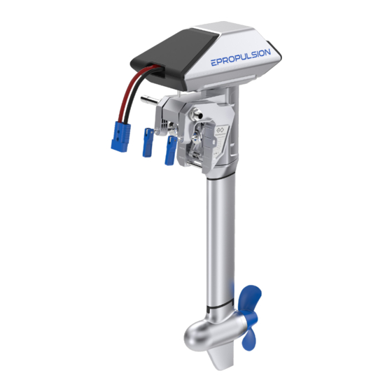
Button Bracket Clamp Trim Lever Communication Port Tightening Handle for Clamp Shaft Propeller Anode Motor Figure 1-1 NAVY 3.0 Main Part Throttle Handle Display Panel Buttons Solar Panel Kill Switch Communication Port (Bottom) Figure 1-2 Remote Control Solar Panel Buttons... -
Page 11: Specification
1.3 Specification NAVY 3.0S / NAVY 3.0L Type Electric Rated Voltage / Current 48V / 62.5A Input Voltage Range 39V ~ 60V DC Maximum Input Power 3KW / 3KW (Forward / Reverse) Comparable Petrol Outboard Maximum Overall Efficiency Rated Rotation Speed 2300rpm Control System Remote / Tiller... -
Page 12: Important Notes
17. Users are responsible to assemble the propeller and steering wheel. If other assembly or disassembly is required, please contact your dealer. ePropulsion accepts no liability for any damage or malfunction caused by operations that violate this manual. -
Page 13: Declaration Of Conformity
Product: NAVY 3.0 Model: NAVY 3.0R-S, NAVY 3.0R-L, NAVY 3.0T-S, NAVY 3.0T-L, NAVY 3.0P, NAVY 3.0C Company Name: Dongguan ePropulsion Intelligence Technology Limited Company Address: Room 202, Bldg.17A, Headquarter No.1, 4th XinZhu Road, SongShan Lake District, Dong Guan, Guang Dong, China... - Page 14 The manufacturer is not responsible for any radio or TV itnerference caused by unauthorized modifications to this equipment. Such modifications could void the user's authority to operate the equipment. Signed by : Shizheng Tao, Chief Executive Officer & Cofounder of Dongguan ePropulsion Intelligence Technology Limited...
-
Page 15: Preparations
3.0 outboard motor for internal information exchange. Users can connect four 12V batteries in series to make a 48V battery set and use it to supply power for NAVY 3.0. Users can also enlarge the battery capacity by parallel configuration. -
Page 16: Mounting The Propeller
When using NAVY Batteries, the batteries will work well once being correctly connected. When using non-ePropulsion batteries, before starting the outboard, users should configure the batteries via the Remote Control for the first time use, otherwise the batteries may not work properly. -
Page 17: Mounting The Outboard Motor
In general, the optimal mounting height is affected by the specific conditions of a boat. In order to get the optimal mounting height, it’s suggested to test running by mounting the outboard at different heights. Please consult your dealer for more information. Transom Height 450mm≥H≥350mm 150mm≥H≥100mm R=130mm Figure 3-1 NAVY 3.0-Shortshaft... -
Page 18: Mounting The Outboard
3.2 Mounting the Outboard Method 1 Rotate the two clamps in clockwise direction to fix the outboard onto transom. Lock Figure 3-2 Figure 3-3 Method 2 Use two screws to fix the outboard to the boat. The dimensions of the two mounting Wholes are shown below. -
Page 19: Mounting The Steering System (R)
3.3 Mounting the Steering System (R) When using the Remote Control, please prepare a steering wheel (not supplied with NAVY 3.0) and mount it on the corresponding position to control the direction. Step2: Mount the Link arm with two M8 nuts. -
Page 20: Connecting The Battery
4 Connecting the Battery 4.1 Connecting a 48V Battery When using a battery, make sure the main switch is off before connection. ① Connect the main switch cables to the battery. ② Connect the main switch cables with the power cables from the outboard. ②... -
Page 21: Connecting A Navy Battery
① First connect the main switch cables to the NAVY Battery. ② Connect the main switch cables with the power cables from the outboard. ③ Connect NAVY 3.0 outboard motor to the NAVY Battery with the communication cable. ③... -
Page 22: Batteries In Series/Parallel
4.3 Batteries in Series/Parallel When connecting four 12V batteries in series to make a 48V battery set to supply power for NAVY 3.0, use bridging cables to connect batteries in series (Figure 4-3). Make sure to connect the main switch cable to battery positive terminal and the other cable to battery negative terminal. -
Page 23: Remote Control / Tiller
5 Remote Control / Tiller The Remote Control/Tiller is used for starting and stopping the NAVY outboard motor, adjusting the speed of the motor, configuring the battery parameters, displaying the system information and messages, etc. The Remote Control/Tiller is powered by either solar power or the built-in lithium battery. - Page 24 Buttons Functions 1. On setting pages, press " " button to save the current settings and switch to the next item. 2. On setting pages, press and hold “ ” button, and the system will save your settings, the display will exit from “OK”...
- Page 25 2. On preference setting page, press and hold “ ” button to enter the battery setting page. Battery setting page 3. On any page, press “ ” button to return home page. If users enter the page without setting any parameters, the current parameters displayed on the page will be saved as user parameters by default.
- Page 26 Icons Functions Hidden: system temperature is in normal range. Blink: system temperature is a little high and the maximum input power of motor has been lowered than 3KW. Over-heat alert Shown constantly: system is over temperature and the outboard will stop working.
-
Page 27: Charging
Icons Functions Displaying real time input power to the system. Throttle Power A blinking “RESET” indicating the throttle should be reset to zero position. 5.2 Charging Both the Remote Control and Tiller have a built-in lithium battery for power supply. The battery will be charged automatically under normal use: get charged by solar power or wired connection. -
Page 28: Charging By Wired Connection
It’s recommended to charge the Remote Control/Tiller by solar power. 5.2.2 Charging by wired connection If the Remote Control/Tiller can’t get enough solar power for a long time, the battery level will run out. In this case, a warning message with an error code E60 (Figure 5-4) will display on the LCD panel to remind you to charge the Remote Control/Tiller. - Page 29 Communication Cable * The communication cable needs to be purchased separately. Figure 5-6 During long-term storage, ensure to charge the Remote Control/Tiller battery every 6 months to avoid over-discharge. After long-term storage, charge the Remote Control/Tiller before use. The communication cable is not included in this package. Please purchase one from your dealer if you choose this charging method.
-
Page 30: Power Adjusting
5.3 Power Adjusting 5.3.1 Power Adjusting for Remote Control The Remote Control is mainly used to adjust the input power of the outboard motor. When the battery is well connected and switched on, power on the Remote Control to start the outboard, then slowly push the throttle forward position to increase the throttle power. -
Page 31: Power Adjusting For Tiller
5.3.2 Power Adjusting for Tiller The Tiller is mainly used for power adjusting and steering control. When the battery is well connected and switched on, power on the Tiller to start the outboard, then turn the throttle gradually form zero position to the forward direction to start. -
Page 32: Recalibration
5.3.3 Recalibration The throttle position sensor should be recalibrated if the below error code displays. Figure 5-9 Recalibration process LCD Displaying Step1: Long press “ ” button for 10s until “CAL FO” displays. Step2: Push/Turn the throttle to the maximum forward power position, then press “... - Page 33 Step4: Pull/Turn the throttle to the maximum backward power position, then press “ ” button. “CAL FO” will display and calibration is completed. A blinking “RESET” will display to remind you to reset the throttle to zero position. Step5: Push/Turn the throttle to zero position and press the “...
-
Page 34: Use Of Kill Switch
5.4 Use of Kill Switch Locate the kill switch to the right place on the Remote/Tiller and tie its lanyard to your wrist or life jacket. Stop the outboard in emergency by detaching the kill switch. To run the motor again, first attach the kill switch then start the motor. Figure 5-10 Figure 5-11 The kill switch generates magnetic field. - Page 35 However, if the Remote /Tiller or the outboard motor is not replaced, but the LCD panel still displays like this, you should check and: 1) Make sure the Remote is not far from the outboard motor; 2) Make sure all the equipment involved is normally powered on. If the Remote /Tiller still displays like Figure 5-12 after check, it indicates an error has occurred.
-
Page 36: Warning Messages
If pairing fails within 60s, go back to Step3 and try again. b. Wired Automatic Pairing Step1: Switch off both NAVY outboard and Remote Control/Tiller. Step2: Connect NAVY outboard and Remote Control/Tiller with a communication cable. Please refer to Figure 5-15 or Figure 5-16. Step3: Switch on both NAVY outboard and Remote Control/Tiller and wait for them to get paired. - Page 37 Figure 5-17 Codes Causes Solutions Battery voltage is over the Replace a battery based on operating range. suggested operation specifications. Propeller may be blocked, Please refer to the solution to E10. causing motor overcurrent Motor fails or circuit Try to turn off the main switch and board fails causing motor wait for 10 seconds then turn on the overcurrent...
- Page 38 Code Cause Solution Stop operating the outboard and wait The temperature of until the temperature falls within the motor is too high. normal operating temperature range. Stop operating the outboard and wait The temperature of until the temperature falls within the circuit board is too high.
- Page 39 Motor and pair the Remote Control/Tiller with the outboard motor again. Buzzer The buzzer beeps when the remaining Normal beeps battery drops to 50%, 20% and 10%. If the problem persists, please consult your ePropulsion authorized dealer for assistance.
-
Page 40: Configurations
Batteries, users should manually configure the batteries via Remote Control/ Tiller at the first time use, otherwise the batteries may not work properly. Battery configuration should be carried out if a battery with different type/capacity/voltage is connected to NAVY 3.0 for the first time. - Page 41 Battery Configuration Process LCD Displaying Step1: First, turn on the main switch and the Remote Control/Tiller. Then, press “ ” button and hold to enter the preference setting page. Next, press “ ” button and hold again to enter the battery setting page. Users can see the voltage value blinking and it’s ready for configuration.
- Page 42 Lithium batteries, lead acid batteries and lithium iron phosphate batteries are recommended to use with NAVY 3.0. Other types of battery may fail to make NAVY 3.0 work properly. When you use the below batteries, please set battery type and rated voltage value based on the parameters in the following table.
-
Page 43: Checklist Before Use
7 Checklist before Use 1. Ensure the propeller is correctly and firmly mounted on the outboard. 2. Ensure the outboard is correctly and firmly mounted on the boat. 3. Ensure the throttle and steering wheel are installed in proper position bef- ore turning on the power. -
Page 44: Starting The Outboard
8 Starting the Outboard 1. Complete the check list. 2. Remove the kill switch from the Remote Control/Tiller. 3. Push/Turn the throttle to zero position. 4. Connect the battery to the outboard. 5. Fix the outboard with a proper trim angle. 6. -
Page 45: Stopping The Outboard
9 Stopping the Outboard Usually, it’s recommended to stop the outboard as the following procedures. 1. Return the throttle to zero position. 2. Wait until the outboard stops, then detach the kill switch from the Remote Controller/Tiller. 3. Press and hold the “ ”button until the Remote Control/Tiller is powered off. -
Page 46: Trim Angle Adjusting
10 Trim Angle Adjusting Only adjust the outboard trim angle when the outboard is stationary. There are five trim angle options including 60°,15°,10°,5° and 0°. Adjust the outboard trim angle based on specific conditions. E.g. when the boat is in shallow water or the outboard is not in use, tilt the outboard and adjust the trim angle to 60°. - Page 47 Tilting Down The release button is raised when the trim angle is maximum at 60° position. Press the release button and tilt up the propeller shaft slightly to about 80° position, then lay it down, and the outboard shaft will return to 0° position. It’s suggested to test with different trim angles to find the optimal trim angle for the boat and operation.
-
Page 48: Maintenance
Disconnect the battery with the outboard before maintenance. Conduct the maintenance work according to the instructions from ePropulsion authorized dealers. Only use ePropulsion original parts for replacement and maintenance. 11.2 Maintenance Time Table Regular maintenance helps to keep the outboard in its optimal operating state. -
Page 49: Propeller Maintenance
11.3 Propeller Maintenance Disconnect the battery with outboard before maintenance. Gloves are recommended to protect your hand from sharp propeller edges. Check the propeller according to the following instructions, then refer to then refer to section 2.2 Mounting the Propeller to replace a new propeller if necessary. -
Page 50: Transportation And Storage
12 Transportation and Storage 12.1 Transport For long distance transport, please use the ePropulsion original packing materials to pack the outboard before delivery. Figure 12-1 12.2 Placement When placing the outboard on a surface, ensure the surface is flat and horizontal. -
Page 51: Emergency Situations
1000W. 13.4 Over-temperature Protection The maximum input power of NAVY 3.0 has been limited to be below 3KW when the system temperature is a little high. If the system temperature continues to be warm and surpasses a threshold, the outboard motor will shut down automatically to avoid over-temperature. -
Page 52: Warranty
14 Warranty The ePropulsion limited warranty is provided for the first end purchaser of an ePropulsion product. Consumers are entitled to a free repair or replacement of defective parts or parts which do not conform with the sales contract. This warranty operates in addition to your statutory rights under your local consumer law. -
Page 53: Out Of Warranty
1. Fill in Warranty Card correctly and completely in advance. Then make your warranty claim by sending it to your authorized ePropulsion service partner together with valid proof of purchase. Usually these documents are required when making a warranty claim: the Warranty Card, ex-factory serial number, and evidence of purchase. - Page 54 3. The defective components or parts will be either repaired or replaced according to the diagnosis made by the ePropulsion authorized service partner. 4. If your warranty claim is accepted, the equipment will be repaired or replaced free of charge. Note that any delivery cost incurred in the process is at your charge.
- Page 56 Thanks for reading this user manual. If you have any concerns or find any problems while reading, please don't hesitate to contact us. We are delighted to offer service for you. ePropulsion Innovation (HK) Ltd. Website: www.epropulsion.com Email: service@epropulsion.com...
Need help?
Do you have a question about the NAVY 3.0 and is the answer not in the manual?
Questions and answers