
Related Manuals for ePropulsion NAVY Evo


Summary of Contents for ePropulsion NAVY Evo
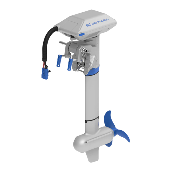
- Page 1 NAVY Evo User Manual Apr, 2021 Version 1.0 Copyright © 2021 ePropulsion. All Rights Reserved...
-
Page 3: Acknowledgement
Before use of the product, please read this user manual thoroughly to understand the correct and safe operations. By using this product, you hereby agree that you have fully read and understood all contents of this manual. ePropulsion accepts no liability for any damage or injury caused by operations that contradict this manual. -
Page 4: Product Identification
Product Identification Below picture indicates the serial numbers of NAVY Evo. Please note the position of the serial numbers and record them for access to warranty service and other af- ter-sale services. Figure 0-1... -
Page 5: Table Of Contents
Table of Contents Acknowledgement ..................1 Using This Manual ..................1 Symbols ....................1 Product Identification ................2 1 Product Overview ................... 6 1.1 In the Package ..................6 1.2 Parts and Diagram................... 8 1.3 Specifications ..................9 1.4 Important Notes ................... 10 1.5 Declaration of Conformity .............. - Page 6 5.4 Use of Kill Switch ................... 32 5.5 Use of Safety Wristband ............... 33 5.5.1 Pairing Safety Wristband with Evo Control System ....33 5.5.2 Man Overboard Protection ............33 5.5.3 Emergency Stop ................33 5.6 Pairing Evo Control System with the Outboard ........34 5.7 Hydro Generation Function ..............
- Page 7 16 Warranty .................... 54 16.1 Warranty Policies................. 54 16.2 Out of Warranty ................... 55 16.3 Warranty Claim Procedures ..............55...
-
Page 8: Product Overview
NAVY 6.0 Evo is a 6kW electric outboard motor, and NAVY 3.0 Evo is a 3kW electric outboard motor. Evo control system is necessary when operating the outboard motor, but it is not included in the NAVY Evo. It need be purchased separately by users from ePro- pulsion authorized dealers. 1.1 In the Package Unpack the package and check if there is any damage caused during transport. - Page 9 Other accessories not included in the package are also required to operate the outboard motor, such as Evo control system, battery, charger and communica- tion cable, etc. Users can buy official accessories provided by ePropulsion such as Evo Remote Control, Evo Tiller, E Series Battery, E battery Charger and com-...
-
Page 10: Parts And Diagram
NAVY 6.0 Evo in the package differ in specifications: the high-pitch propeller (Diameter: 320mm/12.6inch, Pitch: 10.8inch) and the low-pitch propeller (Diameter: 340mm/13.4inch, Pitch: 8.5inch). They share the accessories. Save ePropulsion original package for transport and storage. 1.2 Parts and Diagram Tiller shaft Motor Case... -
Page 11: Specifications
1.3 Specifications NAVY 3.0 Evo-S/L NAVY 6.0 Evo-S/L Type Electric Outboard Motor Input Power 3 kW 6 kW Rated Voltage 48 V Input Voltage 39 V ~ 60 V DC 39 V ~ 60 V DC Equivalent Power 6 hp 9.9 hp Max Overall Efficiency Rated Rotation Speed... -
Page 12: Important Notes
17. Users are responsible to assemble the propeller and steering wheel. If other assembly or disassembly is required, please contact your dealer. ePropulsion accepts no liability for any damage or malfunction caused by operations that violate this manual. -
Page 13: Declaration Of Conformity
Model: NAVY 6.0 Evo, NAVY 6.0 Evo-L, NAVY 6.0 Evo-S, NAVY 6.0 Evo-C, NAVY 3.0 Evo, NAVY 3.0 Evo-L, NAVY 3.0 Evo-S, NAVY 3.0 Evo-C Company Name: Guangdong ePropulsion Technology Limited Address: Room 201, Bldg.17A, 4th XinZhu Road, SongShan Lake District, Dongguan... -
Page 14: Preparations
Lithium-based and lead-acid batteries can be used to supply power for NAVY Evo. Considering the high performance in energy density and discharge ability, lithi- um-based batteries are more preferable. To ensure that NAVY Evo can work at its full power continually, the batteries are required to possess over 62.5A(NAVY 3.0 Evo) or 125A(NAVY 6.0 Evo) of continuous discharge current. -
Page 15: Selecting And Mounting The Propeller
Only use the same batteries (same model, same capacity, same age and same manufacturer) in series or in parallel configuration. Variations in the batteries will cause damage to them. 2.2 Selecting and Mounting the Propeller For NAVY 3.0 Evo, the propeller of NAVY 3.0 Evo is attached on the motor before de- livery. - Page 16 Step1: Attach the Φ16 washer. Step2: Fix the pin to the hole of shaft. Step3: Attach the propeller. Step4: Attach the Φ12 washer. Step5: Tighten the nut with 19mm (3/4 inch) socket wrench. Step6: Attach the Anode. Step7: Attach the Φ6 washer. Step8: Screw and tighten the nut with M6 hexagon wrench.
-
Page 17: Mounting The Outboard Motor
3 Mounting the Outboard Motor Select an outboard with proper shaft length according to the transom height of your boat. The top of the propeller should be 100mm to 150mm below the water. The outboard should be mounted on the centerline of your boat. If the boat shape is asymmetric, please consult your dealer for proper solution. -
Page 18: Mounting The Outboard
3.2 Mounting the Outboard Method 1 Rotate the two clamps in clockwise direction to fix the outboard onto transom. Figure 3-1 Method 2 Use two screws to fix the outboard to the boat. The dimensions of the two mounting holes are shown below. Top of boat transom 10mm 175mm... -
Page 19: Mounting The Steering System
Control in the proper position. When using the Evo Remote Control, please prepare a steering wheel (not supplied with NAVY Evo or the Evo Remote Control) and mount it on the corresponding posi- tion to control the direction. Step2: Mount the Link arm with two M8 nuts. - Page 20 2. Install the tiller to the machine. Figure 3-5 3. Insert the handle shaft into the hole to the end and lock it clockwise. Handle Shaft Figure 3-6 4. Connect the communication cable of Evo Tiller to the communication port of the NAVY Evo. Figure 3-7...
-
Page 21: Connecting The Battery
4 Connecting the Battery 4.1 Connecting a 48V Battery When using a battery, make sure the main switch is off before connection. 1. First connect the main switch cable to the battery. 2. Connect the main switch cables with the power cable from the outboard. ②... -
Page 22: Connecting E Series Batteries
2. Connect the main switch cable to the E Series Battery. 3. Connect the main switch cable with the power cable from the outboard. 4. Connect NAVY Evo outboard motor to the E Series Battery with a communication cable. It's recommended to connect the communication cable to obtain accurate bat- tery information. - Page 23 NAVY Evo outboard motor will stop once the power cable disconnects. Use communication cables to connect E Series Batteries when multiple E Series Batteries are used in parallel.
-
Page 24: Batteries In Series/Parallel
When connecting four 12V batteries in series to make a 48V battery set to supply power for NAVY Evo, use bridging cables to connect batteries in series (Figure 4-3). Make sure to connect the main switch cable to battery positive terminal and the other cable to battery negative terminal. -
Page 25: Evo Remote Control/Evo Tiller
5 Evo Remote Control/Evo Tiller The Evo Remote Control and Evo Tiller is used for starting and stopping the outboard motor, adjusting the speed of the motor, configuring the battery parameters, display- ing the system information and messages, etc. The Evo Remote Control is powered by either solar power or the built-in lithium battery, but the Evo Tiller is powered by connecting to the outboard with a communication cable. - Page 26 Buttons Functions 1. In power-off state, press and hold the power button to power on the Evo Remote Control or Evo Tiller. 2. In power-on state, press and hold the power button to power off "Power" the Evo Remote Control or Evo Tiller. 3. In power-on state, press the power button to switch on or off the backlight of Evo Remote Control or Evo Tiller.
- Page 27 Buttons Functions 1. In power-on state, press and hold “ ” button to enter the preference setting page. Preference setting page 2. On preference setting page, press and hold “ ” button to enter "Menu" the battery setting page. Battery setting page 3. On any page, press “...
- Page 28 Icons Functions Hidden: no satellite signal is received or GPS status GPS does not work. Blink: GPS is connecting to satellites. indicator Shown constantly: GPS is in use. Blink:The motor fan has faults. Please con- Fan fault tact the dealer to check the fan wiring. Hidden: system temperature is in normal range.
- Page 29 Icons Functions Displaying real time input power to the system. Throttle Power A blinking “RESET” indicating the throttle should be reset to zero position. Wireless Displaying the remote control is wireless connecting connecting with outboard. indicator Shown constantly: the safety is connec- ting with the remote control successfully.
-
Page 30: Charging The Evo Remote Control
5.2 Charging the Evo Remote Control The Evo remote control has an in-built lithium battery for power supply. The battery will be charged automatically under normal use: get charged by solar power or wired connection. 5.2.1 Charging by Solar Power When the solar panel receives enough sunshine, it will generate electricity to charge the in-built lithium battery. - Page 31 Battery Communication Cable Figure 5-4 During long-term storage, ensure to charge the control system every 6 months to avoid over-discharge. Do not short-circuit the main switch with other power supplies. The main switch should be mounted on the boat, and the back plate of the main switch should not be removed.
-
Page 32: Power Adjusting
5.3 Power Adjusting 5.3.1 Power Adjusting for Evo Control System Please place the safety switch on the Evo control system before operation. The Evo Control system is mainly used to adjust the input power of the motor. When the battery is well connected and switched on, power on the control system to start the outboard, then slowly push/rotate the throttle forward position to increase the power. -
Page 33: Recalibration
5.3.2 Recalibration If the error code displays as the figure 5-7, users should calibrate the throttle strictly as below steps. Before calibration, please attach the kill switch in the package to the proper posi- tion. It is forbidden to use other magnets to replace the kill switch for calibration. Figure 5-7 Recalibration process LCD Displaying... -
Page 34: Use Of Kill Switch
Recalibration process LCD Displaying Step4: Pull the throttle to the maximum backward power position, then press " " button. “CAL FO” will display and calibration is completed. A blinking “RESET” will dis- play to remind you to reset the throttle to zero position. Step5: Push the throttle to zero position and press the “... -
Page 35: Use Of Safety Wristband
5.5 Use of Safety Wristband 5.5.1 Pairing Safety Wristband with Evo Control System Press the “ ” and “ ” buttons and hold for a while to display the safety wristband icon and “SE”. At this time, approach the safety wristband that needs to be paired, turn on the safety wristband, and the Evo control system displays the “SUC”, indicat- ing successfully pairing. -
Page 36: Pairing Evo Control System With The Outboard
When a wristband is disconnected or an emergency stop is performed, the stop command of other wristbands will not work until it returns to the normal state. 5.6 Pairing Evo Control System with the Outboard Before use please pair control system with the outboard. Evo Tiller will automatically pair with the outboard after mounting on the outboard properly. - Page 37 Method 2. Pairing with Communication Cable Step1: Switch off system power and the remote control. Step2: Connect the remote control and the Communication module with a communi- cation cable. Step3: Switch on system power and the remote control. Wait for them to get paired in seconds.
-
Page 38: Hydro Generation Function
4. The machine will enter the hydro generation state after the boat speed is above 6km/h stable for 4 seconds. 5. The hydro generation function can be used only when connecting ePropulsion batteries. 6. If using E-series battery, please connect with a communication cable. -
Page 39: Warning Messages
5.8 Warning Messages When the outboard motor is running in abnormal conditions or out of order, a warning message with an error code will display on the LCD panel. Figure 6-13 is an example. Please find more error codes and corresponding solutions in the below table. Figure 5-14 Code Cause... - Page 40 The motor has no power. All cha- then turn on the main switch. racters Please refer to section 6.6 Pairing Control display Not paired System with the Outboard. If the problem persists, please consult your ePropulsion authorized dealer for assistance.
-
Page 41: Configurations
6.2 Battery Configuration Accurate battery configuration helps achieve precise estimation of the battery's dis- charging state. When using an ePropulsion E Series Battery, battery configuration is self-activated by the control system given that all the communication cables are well connected. When not using E Series Batteries, users should manually configure the batteries via Remote Control/Tiller at the first time use, so the battery level will dis- play more accurate. - Page 42 Battery Configuration Process LCD Displaying Step1: First, turn on the main switch and the Evo Remote Control / Evo Tiller. Press and hold the “ ” and “ ” button simultaneously to enter the battery setting page. Users can see the attery type blinking and it’s ready for configuration.
- Page 43 Lithium batteries, lead acid batteries and lithium iron phosphate batteries are recommended to use with NAVY Evo. Other types of battery may fail to make NAVY Evo work properly. When you use the below batteries, please set battery type and rated voltage val- ue based on the parameters in the following table.
-
Page 44: Checklist Before Use
7 Checklist before Use 1. Ensure the propeller is correctly and firmly mounted on the outboard. 2. Ensure the outboard is correctly and firmly mounted on the boat. 3. Ensure the throttle and steering wheel are installed in proper position before turning on the power. 4. Ensure the throttle travels smoothly with no obstacles. -
Page 45: Stopping The Outboard
9 Stopping the Outboard Usually, it’s recommended to stop the outboard as the following procedures. 1. Return the throttle to zero position. 2. Wait until the outboard stops, then detach the kill switch from the Remote Control/Tiller Handle. 3. Press and hold the “ ”button until the Remote Control/Tiller Handle is powered off. -
Page 46: Trim Angle Adjusting
10 Trim Angle Adjusting Only adjust the outboard trim angle when the outboard is stationary. There are five trim angle options including 60°,15°,10°,5° and 0°. Adjust the outboard trim angle based on specific conditions. E.g. when the boat is in shallow water or the outboard is not in use, tilt the outboard and adjust the trim angle to 60°. - Page 47 It’s suggested to test with different trim angles to find the optimal trim angle for the boat and operation. Note that the speed should be increased gradually dur- ing the test, and check if there are any abnormal situations. Stop the outboard and decrease the trim angle if necessary.
-
Page 48: Anti-Grounding Mode
11 Anti-grounding Mode When the boat runs in shallow water or in complicated underwater conditions, it may meet grounding dangers. Setting the outboard to anti-grounding mode will protect the outboard motor from damage if the outboard hits submerged reefs or rocks. In anti-grounding mode, the underwater part of the outboard is flexible in tilting direction and the motor will automatically tilt up if it hits something underwater. -
Page 49: Thread The Communication Cable Into The Bellow
12 Thread the communication cable into the bellow In order to protect the cable and the beauty of the machine, it is recommended that when using a 5m communication cable, follow the following operations to thread the communication cable into the bellow: Step 1: Remove the handle shaft, the decorative cover and the upper case, remove the card holder, and thread the cable through the bellow (it is recommended to insert the hard line into the bellow first to help thread the communication cable). - Page 50 Step 3: Install the upper case, and then install the decorative cover, thread through the two cable holes as shown in the figure, and finally connect to the communication port. Figure 12-3...
-
Page 51: Maintenance
Disconnect the battery from outboard before maintenance. Conduct the maintenance under instructions of professional experts or your dealer. Only use ePropulsion original components for replacement and maintenance. 13.2 Maintenance Time Table Regularly maintained in proper manner and used in normal condition, the outboard can work at its optimal state. -
Page 52: Propeller Maintenance
13.3 Propeller Maintenance Disconnect the battery with outboard before maintenance. Gloves are recommended to protect your hand from sharp propeller edges. Check the propeller according to the following instructions, then refer to then refer to section 2.2 Selecting and Mounting the Propeller to replace a new propeller if neces- sary. - Page 53 Anode Figure 13-3...
-
Page 54: Transportation And Storage
14 Transportation and Storage 14.1 Transport For long distance transport, please use the ePropulsion original packing materials to pack the outboard before delivery. Figure 14-1 14.2 Placement When placing the outboard on a surface, ensure the surface is flat and horizontal. It’s better to put some damping cushion underneath. -
Page 55: Emergency Situations
15 Emergency Situations 15.1 Collision If the outboard strikes some object beneath the water, please follow below proce- dures. 1. Stop the outboard immediately and then turn off the main switch. 2. Check the mechanical structure to see if there are damages. 3. Return to the nearest harbor or pier in low power. - Page 56 16 Warranty The ePropulsion limited warranty is provided for the first end purchaser of an ePro- pulsion product. Consumers are entitled to a free repair or replacement of defective parts or parts which do not conform with the sales contract. This warranty operates in addition to your statutory rights under your local consumer law.
- Page 57 Free warranty is not transferable and will not be reissued. Within the limits of the applicable laws, the warranty policies of ePropulsion may update without prior notice. The latest version is available at our website www. epropulsion.com.
- Page 58 2. Send the defective product to your authorized ePropulsion service point after getting the confirmation. Note that the label should be kept intact. You can also deliver the product to your authorized ePropulsion dealer after getting confirmation. 3. The defective components or parts will be either repaired or replaced according to the diagnosis made by the ePropulsion authorized service partner.
- Page 60 Thanks for reading this user manual. If you have any concerns or find any problems while reading, please don't hesitate to contact us. We are delighted to offer service for you. Guangdong ePropulsion Technology Limited Webseite: www.epropulsion.com E-Mail: service@epropulsion.com...
Need help?
Do you have a question about the NAVY Evo and is the answer not in the manual?
Questions and answers