
Related Manuals for Atmel AT89C51ED2


Summary of Contents for Atmel AT89C51ED2
- Page 1 AT89STK-11 Starter Kit ....................Hardware User Guide...
-
Page 2: Table Of Contents
Table of Contents Section 1 Introduction ................... 1-1 Features ....................1-1 Supported Devices..................1-2 Section 2 Hardware Description ................2-4 Board Overview..................2-4 Block Diagram...................2-5 Power Supply ....................2-5 Reset......................2-6 Features ....................2-7 Interfaces ....................2-7 Board Settings ..................2-9 Section 3 ISP Programming ................3-12 Manual ISP Mode ...................3-12 Auto ISP Mode ..................3-12 FLIP Software ..................3-13 Batchisp Software ...................3-13... -
Page 3: Introduction
Section 1 Introduction This document describes the AT89STK-11 board dedicated to the standard C51 micro- controllers with in-system programming. All of the microcontroller I/Os are made available in an expansion area with prototyping facilities. Features Stand-alone Board In-System Programmable (ISP) including ‘Auto ISP’ feature On-board Voltage Regulator Microcontroler on its sockets –... -
Page 4: Supported Devices
Introduction Supported AT89C51RE2 Devices AT89C51RB2 AT89C51RC2/IC2 AT89C51RD2/ID2/ED2 AT89STK-11 Hardware User Guide 7676B–8051–08/07... -
Page 5: Hardware Description
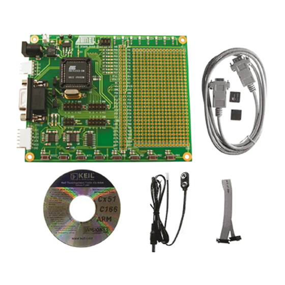
Section 2 Hardware Description Board Overview Figure 2-1 shows the AT89STK-11 board. Figure 2-1. AT89STK-11 This photo is not contractual and may be modified without notification by Atmel. AT89STK-11 Hardware User Guide 7676B–8051–08/07... -
Page 6: Block Diagram
Hardware Description Block Diagram Figure 2-2 shows the functional block diagram of the AT89STK-11, with the I/O usage. Figure 2-2. Block Diagram of AT89STK-11 PC Host Full UART 16MHz Quartz Expansion Area PLCC44 INT0 INT1 Leds: User LEDs User Push Buttons External Power Supply 3V or 5V... -
Page 7: Reset
Note: Keep SP1 closed when using the EXT input Reset To be compatible with Atmel microcontrollers which have (or not) its on-chip RESET cir- cuitry (c.f.microcontroller datasheet), the board provides a RESET signal witch can come from 2 different sources: 2.4.1... -
Page 8: Features
Hardware Description Features This section presents the various features such as leds, buttons, etc... available on the board. 2.5.1 Push-Buttons RESET can be used to apply warm reset to the MCU ISP can be used with RESET to apply hardware conditions resulting in bootloader start INT0 push-button can be used to activate INT0 input INT1 push-button can be used to activate INT1 input... -
Page 9: Board Settings
Hardware Description This interface enables the debug of the application through ATMEL OCD dongle for AT89C51RE2/IE2/RD3/IE3 only. 2.6.5 Expansion Area In addition to a 16x29 pad array, two rows of pads are given on the right side of the board to offer all the MCU signals tu user application. Any application expansion can be built on board through this interface. - Page 10 Hardware Description Figure 2-6. Solder Strap Definition 2.7.3 Test Points Test points are used to check the internal power supply of the microcontroller. Table 2-3. Table of Test Points Reference PCB Label Function Test point for Vcc TP2,TP3 Test point for GND AT89STK-11 Hardware User Guide 7676B–8051–08/07...
-
Page 11: Isp Programming
ISP mode. Auto ISP Mode It allows the host PC application (Atmel Flip software for example) to control the hard- ware conditions from the serial lines RTS and DTR. Thus with the Auto ISP mode, the user does not need to push the ISP and RESET buttons. -
Page 12: Flip Software
Operating Systems. FLIP supports in-sys- tem programming of Flash C51 devices through RS232. The latest version of FLIP software can be downloaded from the Atmel web site, www.atmel.com. Batchisp Batchisp is an In-System Programming application which can perform the same opera- Software tions as FLIP but is designed to be launched from the DOS command window. -
Page 13: Appendix A: Board Layout
Section 4 Appendix A: Board Layout Figure 4-1. Board Components View Diagram AT89STK-11 Hardware User Guide 4-12 7676B–8051–08/07... -
Page 14: Appendix B: Bill Of Materials
Appendix B: Bill of Materials Bill of Materials Table Item Q.ty Reference Part Tech. Caracteristics Package Manufacturer CD1,CD2,C2,CD3,C3,C4, CD5,C5,CD6,C6,CD7,C7,C8, C9,C10,C11,C12,C13,C16, 100n 50V-10% Ceramic CASE 0805 PHYCOMP C17,C18,C19,C20,C21,C22, C23,C24,C25,C26 1 C1 1µF 10Vmin ±10% Case A EIA/IECQ 2 C14,C15 22pF 10Vmin ±10% PHYCOMP 3216 ®... - Page 15 Appendix B: Bill of Materials Item Q.ty Reference Part Tech. Caracteristics Package Manufacturer 3 TP1,TP2,TP3 TEST POINT Through Hole Pad Hole 1.1mm Vero ® 1 U1 DF005S TO269AA Vishay ® 1 U2 LM317 SOT-223 National 1 U6 AT8xC51_PLCC44 Socket 25bis 1 U6 AT8xC51_PLCC44 ®...
-
Page 16: Appendix C: Board Schematics
Appendix C: Board Schematics AT89STK-11 Hardware User Guide 4-15 7676B–8051–08/07... - Page 17 Appendix C: Board Schematics Figure 4-2. AT89STK-11 Schematics (1 of 4) AT89STK-11 Hardware User Guide 4-16 7676B–8051–08/07...
- Page 18 Appendix C: Board Schematics Figure 4-3. AT89STK-11 Schematics (2 of 4) 4-17 AT89STK-11 Hardware User Guide 7676B–8051–08/07...
- Page 19 Appendix C: Board Schematics Figure 4-4. AT89STK-11 Schematics (3 of 4) AT89STK-11 Hardware User Guide 4-18 7676B–8051–08/07...
- Page 20 Appendix C: Board Schematics Figure 4-5. AT89STK-11 Schematics (4 of 4) 4-19 AT89STK-11 Hardware User Guide 7676B–8051–08/07...
-
Page 21: Appendix D: References/Acronyms
Appendix D: References/Acronyms References AT89C51RD2/ID2/ED2/RB2/RC2/IC2/RE2/IE2 and AT89C51RD3/IE3 Product Datasheet. Acronyms FLIP: FLexible In-system Programming ISP: In-System programming AT89STK-11 Hardware User Guide 4-20 7676B–8051–08/07... -
Page 22: Acronyms
Appendix D: References/Acronyms Document Revision History Changes from 7676A to 1. Section 1.2, page 1-2 : AT89C51RE3/ID3/IE2 not supported. 7676B 2. Section 2.3.1.2, page 2-5 : SP1 must be kept closed. 3. Section 3.1.1, page 3-11 : SW1 switch and EA jumper do not exist. 4. - Page 23 Disclaimer: The information in this document is provided in connection with Atmel products. No license, express or implied, by estoppel or otherwise, to any intellectual property right is granted by this document or in connection with the sale of Atmel products. EXCEPT AS SET FORTH IN ATMEL’S TERMS AND CONDI- TIONS OF SALE LOCATED ON ATMEL’S WEB SITE, ATMEL ASSUMES NO LIABILITY WHATSOEVER AND DISCLAIMS ANY EXPRESS, IMPLIED OR STATUTORY...
Need help?
Do you have a question about the AT89C51ED2 and is the answer not in the manual?
Questions and answers