
Related Manuals for Atmel ATPL250A


Summary of Contents for Atmel ATPL250A
- Page 1 ATPL250A PANCoordinator-EK Kit User Manual USER GUIDE Atmel-43106C-ATPL- PANCoordinator-EK Kit User Manual-UserGuide_06-Oct-16...
- Page 2 Features ATPL250A is a compact and high-efficient device for a wide range of Smart Grid applications such as Smart Metering (Smart Meters and Data Concentrators), Lighting, Industrial/Home Automation, Home and Building Energy Management Systems, Solar Energy and Plug-in Hybrid Electric Vehicle (PHEV) Charging Stations .
- Page 3 Software application examples available based on G3-PLC Stack: – Atmel provides an Atmel G3-PLC PHY layer library which is used by the external MCU to take control of ATPL250A PHY layer device. Three G3-PLC PHY layer example projects are provided with the kit.
-
Page 4: Table Of Contents
Hardware description .......................... 17 3.5.1 Power supply .......................... 17 3.5.2 Zero crossing detector ......................18 3.5.3 SAME70Q21 Flash microcontroller ..................18 3.5.4 ATPL250A PLC Transceiver ....................19 3.5.5 PLC Coupling.......................... 20 3.5.6 Peripherals..........................22 3.5.7 Interface Ports ........................23 ATPLCOUP007 Hardware ..................26 Overview ............................. - Page 5 7.2.1 Atmel PLC PHY Tester tool Installation .................. 37 7.2.2 Supplying the boards ......................39 7.2.3 USB connection ........................40 7.2.4 Programming the embedded file ..................... 41 7.2.5 Running the PLC application example 1 ................. 43 PLC application example 2 – PHY TX Test Console ................55 7.3.1...
- Page 6 Actions to be Executed Out of the Target The Expected Result of an Assignment Step Procedure Which Can Result in Minor Equipment Damage Procedure With Potential Equipment Damage Procedure With Imminent Equipment Destruction PANCoordinator-EK Kit User Manual [USER GUIDE] Atmel-43106C-ATPL- PANCoordinator-EK Kit User Manual-UserGuide_06-Oct-16...
-
Page 7: Evaluation Kit Specifications
EN50065-7 EMC and FCC (as current carrier system) standards. It also satisfies Pb-Free and ROHS directive. ATMEL does not assume responsibility for the consequences arising from any improper use of this board. Boards’ kits are intended for further engineering, development, demonstration, or evaluation purposes only. - Page 8 These measurements correspond to the whole PCBA design and not only to ATPL250A and ATSAME70 devices. All PCB peripherals are supplied, i.e. ATPLCOUP007 coupling board emitting in CENELEC-A band. Refer to Atmel ATPL250A and ATSAME70 datasheets for an optimized power consumption measurement result.
-
Page 9: Evaluation Kit Overview
ATPL250ABN is the name of the development board included in this PAN Coordinator EK. It implements an ATPL250A analog front end for PLC, supporting G3-PLC, which has been designed to be controlled by an external Atmel MCU. In this case, Atmel | Smart SAME70 is the device driving ATPL250A PLC analog front end. - Page 10 Evaluation License Agreement document. 5. PCTools folder: a. Atmel PLC PHY Tester, PC tool used to monitor point to point PLC transmissions between Atmel boards. b. ATPL Multiprotocol Sniffer, PC tool to monitor data traffic in G3-PLC networks using an Atmel board as sniffer.
- Page 11 ATPL250ABN board is provided with an example application preprogrammed, the G3-PLC PHY Tester project for SAM4E70Q21. After installing the Atmel PLC PHY Tester PC Tool in your PC, users can interface with the device and start exploring its capabilities, for example, checking the point to point PLC transmissions between the two Atmel boards.
- Page 12 Figure 2-3. ATPLCOUP007 Coupling board. Figure 2-4. ATPLCOUP002 Coupling board. Figure 2-5. ATPLCOUP006 Coupling board. PANCoordinator-EK Kit User Manual [USER GUIDE] Atmel-43106C-ATPL- PANCoordinator-EK Kit User Manual-UserGuide_06-Oct-16...
-
Page 13: Atpl250Abn Hardware
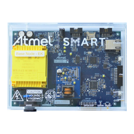
This section summarizes the Atmel ATPL250ABN board design. It introduces system-level concepts, such as power supply, MCU, PLC coupling, memories, peripherals and interface board. ATPL250ABN is a PAN Coordinator development board based on the ATPL250A, G3-PLC transceiver, and on the SAME70 ARM Cortex M7 microcontroller. ATPL250ABN PAN Coordinator board provides a platform to develop a complete communications system over G3-PLC technology. - Page 14 MCU 32.768 kHz crystal oscillator. – and 5V Voltage monitor. – Reset button. – User’s LEDs. – Chip erase. Interface: – JTAG debugging port. – Embedded Trace Module (ETM). PANCoordinator-EK Kit User Manual [USER GUIDE] Atmel-43106C-ATPL- PANCoordinator-EK Kit User Manual-UserGuide_06-Oct-16...
- Page 15 UARTs over USB and CMOS levels. – Ethernet 10/100 Mbps. – Poly-phase Base Node extension header. – Data Concentrator extension header. – GPIOs extension header. Figure 3-2. ATPL250ABNv2 PAN Coordinator board overview. PANCoordinator-EK Kit User Manual [USER GUIDE] Atmel-43106C-ATPL- PANCoordinator-EK Kit User Manual-UserGuide_06-Oct-16...
-
Page 16: Block Diagram
ATPL250ABN dimensions are 178mm x 124mm x 30mm (LxWxH) and the enclosure dimensions are 191mm x 140mm x 48mm (LxWxH). The operating temperature range is about -10 to 85ºC. PANCoordinator-EK Kit User Manual [USER GUIDE] Atmel-43106C-ATPL- PANCoordinator-EK Kit User Manual-UserGuide_06-Oct-16... -
Page 17: Hardware Description
5V voltage rail. Despite 5V is not used by any device on ATPL250ABN board, it may be useful to power other Atmel evaluation kits to form more complex PLC reference designs, such as data concentrators. The DC Jack connector J15 (J15, Figure A-10) can be used to connect other board to 5V. -
Page 18: Zero Crossing Detector
The output signal of the detection circuit “VNR” is connected to a specific input of the ATPL250A and a synchronization algorithm is applied in order to obtain an accurate measurement of the time between PLC frame reception and zero crossing events. -
Page 19: Atpl250A Plc Transceiver
(Y1, Figure A-7). The 24MHz clock signal could be used as internal reference time of the PLC modem, ATPL250A, and also to generate a 12MHz. So, it could be connected the output clock signal (CLKOUT) of ATPL250A like an input clock (CLKIN) of SAME70Q21 when ATPL250A is configured in bypass mode. -
Page 20: Plc Coupling
3.5.5 PLC Coupling Atmel PLC technology is purely digital and does not require external DAC/ADC, thus simplifying the external required circuitry. Generally Atmel PLC coupling reference designs make use of few passive components plus a Class D amplification stage for transmission. - Page 21 A set of boards known as ATPLCOUPxxx have been design by to support multiple transmission options supported by ATPL250A. PANCoordinator-EK includes ATPLCOUP007, ATPLCOUP002 and ATPLCOUP006 boards which are described in chapters 4, 5 and 6 respectively.
-
Page 22: Peripherals
Two different packages (U3 and U12, Figure A-4) are used in ATPL250ABN board to support the pinout of both the Adesto (former Atmel) family of DataFlash memories and standard serial flash products. Since both packages use the same chip select signal, only one device can be assembled simultaneously. -
Page 23: Interface Ports
In addition to the complete reset of the PLC transceiver generated by an assertion of the “PLL_INIT” input, the “ARST” and “SRST” input reset signals allow also resetting the ATPL250A but in each of these cases without disabling the external clock on “CLKOUT” pin. Therefore, no special configurations have to be considered on the microcontroller side related to the clock system configuration. - Page 24 The UART0 of ATSAME70Q21 is connected to a CP2105 UART to USB 2.0 bridge to ease PC connectivity for debugging purposes. The firmware projects provided by Atmel to ease the evaluation of the G3 PHY-layer performance are based on serial interface through UART0.
- Page 25 The 2.54mm pitch right-angle header J12 offers access to the I/O ports of the microcontroller that are not used within the ATPL250ABN board. Refer to ATSAME70Q21 datasheet for a description of the peripheral functionality available of each GPIO. PANCoordinator-EK Kit User Manual [USER GUIDE] Atmel-43106C-ATPL- PANCoordinator-EK Kit User Manual-UserGuide_06-Oct-16...
-
Page 26: Atplcoup007 Hardware
Low impedance optimized. Figure 4-2. ATPLCOUP007v2.5 PLC Coupling board (top view). Test point. Test point. Test point. TX led indication. PLC transformer provides the voltage isolation from mains. Test point. PANCoordinator-EK Kit User Manual [USER GUIDE] Atmel-43106C-ATPL- PANCoordinator-EK Kit User Manual-UserGuide_06-Oct-16... -
Page 27: Mechanical And User Considerations
J16 must be set (see section 3.5.1 and Figure A-2). By default, the jumper is placed in J16. Figure 4-3. V selection in ATPL250ABN board. Jumper configuration PANCoordinator-EK Kit User Manual [USER GUIDE] Atmel-43106C-ATPL- PANCoordinator-EK Kit User Manual-UserGuide_06-Oct-16... -
Page 28: Atplcoup002 Hardware
Figure 5-2. ATPLCOUP002v2 PLC Coupling board. Test point. Test point. Test point. TX Led indication. PLC transformer provides the voltage isolation from mains. TX Led indication. Test point. PANCoordinator-EK Kit User Manual [USER GUIDE] Atmel-43106C-ATPL- PANCoordinator-EK Kit User Manual-UserGuide_06-Oct-16... -
Page 29: Mechanical And User Considerations
J20 must be set (see section 3.5.1 and Figure A-2). By default, the jumper is placed in J16. Figure 5-3. V selection in ATPL250ABN board. Jumper configuration PANCoordinator-EK Kit User Manual [USER GUIDE] Atmel-43106C-ATPL- PANCoordinator-EK Kit User Manual-UserGuide_06-Oct-16... -
Page 30: Atplcoup006 Hardware
High impedance optimized. Figure 6-2. ATPLCOUP006v2 PLC coupling board. Test point. Test point. Test point. TX led indication. PLC transformer provides the voltage isolation from mains. TX led indication. Test point. PANCoordinator-EK Kit User Manual [USER GUIDE] Atmel-43106C-ATPL- PANCoordinator-EK Kit User Manual-UserGuide_06-Oct-16... -
Page 31: Mechanical And User Considerations
J20 must be set (see section 3.5.1 and Figure A-2). By default, the jumper is placed in J16. Figure 6-3. V selection in ATPL250ABN board. Jumper configuration PANCoordinator-EK Kit User Manual [USER GUIDE] Atmel-43106C-ATPL- PANCoordinator-EK Kit User Manual-UserGuide_06-Oct-16... -
Page 32: Pan Coordinator Evaluation Kit: Getting Started
The purpose of this section is to guide new users through the initial settings of IAR Embedded Workbench, Atmel Studio (AS) or Keil µVision, and compile a G3 project. The section shows setup of a G3 project to generate a debug target that can be loaded into the microcontroller. -
Page 33: Atmel Sam-Ice Jtag Probe
C/C++ or assembly code. Atmel Studio 6 is free of charge and is integrated with the Atmel Software Framework (ASF) — a large library of free source code with 1,600 ARM and AVR project examples. ASF strengthens the IDP by providing, in the same environment, access to ready-to-use code that minimizes much of the low-level design required for projects. - Page 34 If the driver is installed and your SAM-ICE is connected to your computer, the device manager should list the J-Link driver as a node below "Universal Serial Bus controllers" as shown in the following screenshot. PANCoordinator-EK Kit User Manual [USER GUIDE] Atmel-43106C-ATPL- PANCoordinator-EK Kit User Manual-UserGuide_06-Oct-16...
-
Page 35: Atmel Software Framework (Asf)
ASF is designed to be used for evaluation, prototyping, design and production phases. The intention of ASF is to provide a rich set of proven drivers and code modules developed by Atmel experts to reduce customer design-time. It simplifies the usage of microcontrollers, providing an abstraction to the hardware and high-value middleware. -
Page 36: Plc Application Example 1 - Phy Tester
SAME70Q21 device, apps_phy_tester_tool.bin. It is an application example that shows the capabilities of the ATPL250A in a point-to-point connection (physical layer). This application requires a pair of boards and a PC tool, Atmel PLC PHY Tester tool, which has to be installed in the user’s host PC to interface with the board. -
Page 37: Atmel Plc Phy Tester Tool Installation
7.2.1 Atmel PLC PHY Tester tool Installation To install Atmel PLC PHY Tester tool in a Windows Operating System, execute the provided installer in the Tools folder: “.\PCTools\ATMEL_PLC_PHY_Tester\ATMEL_PLC_PHY_Tester_Tool_vX.Y.Z.exe”, and follow the installation wizard. The installer wizard should open. To follow with the installation, click Next. - Page 38 Select the users’ permissions and click Next. Figure 7-6. Installation process, slide 2. Click I Agree to continue. Figure 7-7. Installation process, slide 3. Click Next. PANCoordinator-EK Kit User Manual [USER GUIDE] Atmel-43106C-ATPL- PANCoordinator-EK Kit User Manual-UserGuide_06-Oct-16...
-
Page 39: Supplying The Boards
Now the program is installed in your computer and a shortcut should have been created in your desktop. Note that Atmel releases of G3-PLC versions lower than 1.2.2 run with PHY Tester PC Tool version 2.4.6. Atmel G3-PLC version 1.2.2 or above run with PHY Tester PC Tool version 2.5.0 or above. -
Page 40: Usb Connection
7.2.3 USB connection By default, the programmed firmware for Atmel PHY Tester tool establishes serial communication with UART0. Boards have such UART0 available either by micro-B USB connector, J9, or the triple pin row CMOS connector, J16. See the Figure 3-2 and section 3.5.7.4 for more information about the USB device. -
Page 41: Programming The Embedded File
To be able to develop applications, build binaries and program the firmware on the SAME70Q21 device, you can use the IAR Workbench, Keil µVision or Atmel Studio. For that, open the IDE tool used, select the PHY Tester tool project and now build it to generate the output file. - Page 42 In case of programming with Atmel Studio IDE, select the interface to download the output file. By default, JTAG option is selected. That option is found in Tool tab of Device (ATSAME70Q21) button toolbar. See the following figure.
-
Page 43: Running The Plc Application Example 1
Running the PLC application example 1 The Atmel PLC PHY Tester tool is used to control the application running on the SAME70Q21+ATPL250A. As you can see in Figure 7-15, the two boards are plugged into the same power line. Users have to execute two instances of the PHY Tester tool –... - Page 44 A new Tab (Product Information) is appended to the wizard and Next button is enabled allowing the user to go to the following step of the configuration. See Figure 7-18. PANCoordinator-EK Kit User Manual [USER GUIDE] Atmel-43106C-ATPL- PANCoordinator-EK Kit User Manual-UserGuide_06-Oct-16...
- Page 45 Welcome tab. Now press Disconnect button and check your connections. Either you have not selected the right Enhanced COM port or the board is not PANCoordinator-EK Kit User Manual [USER GUIDE] Atmel-43106C-ATPL- PANCoordinator-EK Kit User Manual-UserGuide_06-Oct-16...
- Page 46 The showed information is related to the physical layer implemented in the firmware of the board: Product ID: it shows a text string that identifies the Atmel PLC product (platform). Model ID: It is a 16-bit unsigned integer that identifies the model of the board.
- Page 47 Time Interval (milliseconds): expected interval between frame transmissions. Number of Frames: number of frames to be received. Message: ASCII message expected. Default parameters (100ms and 100 frames) are selected. PANCoordinator-EK Kit User Manual [USER GUIDE] Atmel-43106C-ATPL- PANCoordinator-EK Kit User Manual-UserGuide_06-Oct-16...
- Page 48 Figure 7-22. RX test parameters. Default parameters are selected. Click the Next button to continue. Figure 7-23. Configuration Summary tab. PANCoordinator-EK Kit User Manual [USER GUIDE] Atmel-43106C-ATPL- PANCoordinator-EK Kit User Manual-UserGuide_06-Oct-16...
- Page 49 Note that there is a timeout to wait the frame reception. Figure 7-24. Test Execution tab. Once the receiver board has been configured, the emitter board must be configured. Launch another Atmel PLC PHY Tester tool and once the transmission board is supplied and USB cable connected, configure the corresponding COM port for the board in the window Starting Window.
- Page 50 Modulation Scheme. Allow to configure differential or coherent modulation scheme. Modulation Type. Allow to select between BPSK, QPSK, 8PSK and robust BPSK. PANCoordinator-EK Kit User Manual [USER GUIDE] Atmel-43106C-ATPL- PANCoordinator-EK Kit User Manual-UserGuide_06-Oct-16...
- Page 51 Cenelec-A (36), FCC (72) and ARIB (54). Or Custom if you want to select other range frequencies. If you do not use the tone mask feature select None. Click the Next button to continue. Figure 7-27. TX Test Parameters tab. PANCoordinator-EK Kit User Manual [USER GUIDE] Atmel-43106C-ATPL- PANCoordinator-EK Kit User Manual-UserGuide_06-Oct-16...
- Page 52 During the transmission process the TX led of the coupling board is toggled. You can use it to check if the PLC messages are sent. When all frames are sent, both Test Executions windows show some statistics. See the following figures. PANCoordinator-EK Kit User Manual [USER GUIDE] Atmel-43106C-ATPL- PANCoordinator-EK Kit User Manual-UserGuide_06-Oct-16...
- Page 53 Figure 7-29. Transmission test result. PANCoordinator-EK Kit User Manual [USER GUIDE] Atmel-43106C-ATPL- PANCoordinator-EK Kit User Manual-UserGuide_06-Oct-16...
- Page 54 It is the received info in ASCII format. Interval frame and the previous one. It is the interval of time between the reception Interval of the current frame and the previous one. PANCoordinator-EK Kit User Manual [USER GUIDE] Atmel-43106C-ATPL- PANCoordinator-EK Kit User Manual-UserGuide_06-Oct-16...
-
Page 55: Plc Application Example 2 - Phy Tx Test Console
(apps_phy_tx_test_console.bin) that eases the configuration of several transmission parameters such as modulation, frame data length and time interval between frames. To run this example, two boards are used. So another Atmel board besides of ATPL250ABN is necessary to run this test, e. g, ATPL250AMB. -
Page 56: Supplying The Boards
PC’s hard-disk. Then, assign this new driver from Windows Device Manager. 7.3.3 Programming the embedded file We have commented in section 7.2.4 the way to program a board. Open the IDE tool used, Keil, Atmel Studio or IAR Embedded Workbench. Select the PHY sniffer tool project, apps_phy_tx_test_console.atsln, apps_phy_tx_test_console.eww, apps_phy_tx_test_console_flash.uvprojx, and now build it to generate the output file. -
Page 57: Running The Plc Application Example 2
Note that kits do not provide a J-Link ARM or SAM-ICE JTAG probe in order to connect to the user’s host PC and the boards to download and debug the projects. In case of programming with Atmel Studio IDE, select the interface to to download the output file. By default, JTAG option is selected. - Page 58 Once board is supplied, leds LED0 and LED1 blink once at the same time, after that, green led D5, LED0, blinks quickly several times. Finally main menu is displayed (press Reset button in case board has been PANCoordinator-EK Kit User Manual [USER GUIDE] Atmel-43106C-ATPL- PANCoordinator-EK Kit User Manual-UserGuide_06-Oct-16...
- Page 59 Data: 1. It is Random Data to transmit of 133 bytes. 133 bytes is the maximum for Robust mode in CENELEC. TX tone map: 0x3F. TX preemphasis: 0. Branch mode: Autodetection. Time period: 5400. 5400µs between messages to transmit. Data Len: 100 bytes PANCoordinator-EK Kit User Manual [USER GUIDE] Atmel-43106C-ATPL- PANCoordinator-EK Kit User Manual-UserGuide_06-Oct-16...
- Page 60 During the transmission, green led (LED0) is blinking indicating test is running. And the yellow led, PLC, on ATPLCOUP007 board blinks every time a PLC frame is sent. In the reception board, the red led (LED1) blinks in every PLC frame reception. PANCoordinator-EK Kit User Manual [USER GUIDE] Atmel-43106C-ATPL- PANCoordinator-EK Kit User Manual-UserGuide_06-Oct-16...
-
Page 61: Plc Application Example 3 - Phy Sniffer
The circuitry in the coupling boards has an influence in the reception itself. As a consequence, each coupling board is intended to be used in their corresponding frequency band(s) only. The application behaves properly when this correspondence is maintained. PANCoordinator-EK Kit User Manual [USER GUIDE] Atmel-43106C-ATPL- PANCoordinator-EK Kit User Manual-UserGuide_06-Oct-16... -
Page 62: Atpl Multiprotocol Sniffer Tool Installation
The installer wizard should open. To follow the installation, click Next. Figure 7-39. ATPL Multiprotocol Sniffer installation process, slide 1. Select the users’ permissions and click Next. PANCoordinator-EK Kit User Manual [USER GUIDE] Atmel-43106C-ATPL- PANCoordinator-EK Kit User Manual-UserGuide_06-Oct-16... - Page 63 Read and accept term and conditions expressed in the End User License Agreement. Click I Agree continue. Figure 7-41. Installation process, slide 3. Click Next to install the component selected. PANCoordinator-EK Kit User Manual [USER GUIDE] Atmel-43106C-ATPL- PANCoordinator-EK Kit User Manual-UserGuide_06-Oct-16...
-
Page 64: Supplying The Boards
Please refer to 7.2.2 in order to know how to supply the ATPL250ABN board. 7.4.3 USB connection This application uses UART0, please refer to 7.2.3 in order to know how to connect the micro USB cable with the ATPL250ABN board. PANCoordinator-EK Kit User Manual [USER GUIDE] Atmel-43106C-ATPL- PANCoordinator-EK Kit User Manual-UserGuide_06-Oct-16... -
Page 65: Programming The Embedded Files
We have commented in section 7.2.4 the way to program a board. To program the board as PLC sniffer, process will be the same: building the IDE project and downloading into the board. Open the IDE tool used, Keil, Atmel Studio or IAR Embedded Workbench. Select the project apps_phy_sniffer_tool.atsln apps_phy_sniffer_tool.eww... - Page 66 And it is possible to build your own scripts (for example, in Python) to analyze the data. PANCoordinator-EK Kit User Manual [USER GUIDE] Atmel-43106C-ATPL- PANCoordinator-EK Kit User Manual-UserGuide_06-Oct-16...
- Page 67 Pause command will stop the update of the scroll view, while the logging process will continue. To restart showing the live stream of PDUs, click Play button. Figure 7-49. Tool bar. PANCoordinator-EK Kit User Manual [USER GUIDE] Atmel-43106C-ATPL- PANCoordinator-EK Kit User Manual-UserGuide_06-Oct-16...
-
Page 68: Introduction To G3 Stack
The adaptation layer based on IETF RFC 4944. In the following sections there are basic overviews of the Atmel libraries used and the description of the whole system integration (FreeRTOS, G3-PLC stack, ATPL250A and the SAME70) in a G3 project using the ASF structure. -
Page 69: Asf Integration
Please take into account that the provided RTOS support is just an example of inte- gration of the stack in an RTOS. It is functional, but Atmel does not ensure the same reliability and performance as the microcontroller mode implementation, as the latter is the reference implementation. -
Page 70: Atmel G3-Plc Stack Structure
Layer (ITU-T G.9903) The Atmel G3 stack is able to run on a system with an OS (the OS Wrapper is an abstraction layer so different OSS can be used), or without it, running in microcontroller mode (mode by default). - Page 71 PAL layer, but communicating with a Serial Port Service, instead of the MAC. PHY Tester and PHY Sniffer projects use this serialization to communicate with the PC. The following figure shows the architecture of the Atmel G3 software stack to be placed over the ATPL250A platform.
-
Page 72: Plc Application 4 - Plc Network
PLC application 4 – PLC Network In this chapter the example proposed is used to show the capabilities of the ATPL250A in a network of smart devices. One ATPL250ABN board acts as a PAN Coordinator, i.e. the device that controls the whole network, whereas the other one, e. - Page 73 The syntax in the script file is the same as when using regular commands in J-Link commander (one line per command). To do easier to load the EUI64, Atmel provides you a script, writeEUI64_SAME70Q21.bat, that lets you download the EUI64 in the right memory address position. You can find them in the following directories: “\Software\G3_va.b.c\Scripts\EUI64”.
-
Page 74: Running The Plc Application Example 4
COM port number assigned to the micro-B USB cable (see Figure 7-54). As is commented in section 7.3.2, UART1 CMOS signals are also in the Data Concentrator Expansion connector, J4, see Figure A-10. PANCoordinator-EK Kit User Manual [USER GUIDE] Atmel-43106C-ATPL- PANCoordinator-EK Kit User Manual-UserGuide_06-Oct-16... - Page 75 USB cable), see Figure 7-56. Once coordinator board has been supplied after 4 minutes (time defined in dlms_emu_coord.h) to the bootstrap process it starts the cycle process. PANCoordinator-EK Kit User Manual [USER GUIDE] Atmel-43106C-ATPL- PANCoordinator-EK Kit User Manual-UserGuide_06-Oct-16...
- Page 76 Number of Cycles OK If the PAN Device is not an Atmel board, only runs the bootstrap process, due to DLMS emulation process will be ignored. For more information about the DLMS Emulation procedure see the Atmel G3 Firmware Stack, doc43081.
-
Page 77: References
[3] Narrowband OFDM PLC specifications for G3-PLC networks, 2014. [4] doc43079: ATPL250A Datasheet, 2016. [5] doc11296: SAME70 Series Datasheet, 2016. [6] doc43081: Atmel G3-PLC Firmware Stack User Guide, 2016. [7] ITU G.9901: http://www.itu.int/rec/T-REC-G.9901/en. [8] ITU G.9903: https://www.itu.int/rec/T-REC-G.9903/en. [9] G3-PLC Alliance: http://www.g3-plc.com/. -
Page 78: Appendix A Board Schemes
Power supply scheme. SAME70. Memory. USB. Ethernet. ATPL250A. PLC Coupling TX. PLC Coupling RX. Connectors. Components location in top and bottom layers. PANCoordinator-EK Kit User Manual [USER GUIDE] Atmel-43106C-ATPL- PANCoordinator-EK Kit User Manual-UserGuide_06-Oct-16... - Page 79 ATPL250ABN Top level scheme. PAGE DESIGNATOR DEFAULT FUNCTION 230Vac position 115/230Vac selection Open (16V) Vdd 16/12V selection Close Close to enable 3V3 Open Erase flash memory Figure A-2. ATPL250ABN Power supply scheme. PANCoordinator-EK Kit User Manual [USER GUIDE] Atmel-43106C-ATPL- PANCoordinator-EK Kit User Manual-UserGuide_06-Oct-16...
- Page 80 Figure A-3. SAME70Q21 scheme. Figure A-4. ATPL250ABN Memory scheme. PANCoordinator-EK Kit User Manual [USER GUIDE] Atmel-43106C-ATPL- PANCoordinator-EK Kit User Manual-UserGuide_06-Oct-16...
- Page 81 Figure A-5. ATPL250ABN USB scheme. Figure A-6. ATPL250ABN Ethernet scheme. PANCoordinator-EK Kit User Manual [USER GUIDE] Atmel-43106C-ATPL- PANCoordinator-EK Kit User Manual-UserGuide_06-Oct-16...
- Page 82 Figure A-7. ATPL250A scheme. Figure A-8. ATPL250ABN PLC Coupling transmission scheme. PANCoordinator-EK Kit User Manual [USER GUIDE] Atmel-43106C-ATPL- PANCoordinator-EK Kit User Manual-UserGuide_06-Oct-16...
- Page 83 Figure A-9. ATPL250ABN PLC Coupling reception scheme. Figure A-10. ATPL250ABN Connectors. PANCoordinator-EK Kit User Manual [USER GUIDE] Atmel-43106C-ATPL- PANCoordinator-EK Kit User Manual-UserGuide_06-Oct-16...
- Page 84 Figure A-11. ATPL250ABN components location in top layer. Figure A-12. ATPL250ABN components location in bottom layer. PANCoordinator-EK Kit User Manual [USER GUIDE] Atmel-43106C-ATPL- PANCoordinator-EK Kit User Manual-UserGuide_06-Oct-16...
-
Page 85: Atplcoup007V2.5 Schemes
ATPLCOUP007v2.5 schemes This section contains the schemes of the ATPLCOUP007 board: PLC Coupling transmission scheme. Components location in top and bottom layers. PANCoordinator-EK Kit User Manual [USER GUIDE] Atmel-43106C-ATPL- PANCoordinator-EK Kit User Manual-UserGuide_06-Oct-16... - Page 86 Figure A-13. ATPLCOUP007 PLC Coupling transmission scheme. Figure A-14. ATPLCOUP007 components location in top and bottom layers. PANCoordinator-EK Kit User Manual [USER GUIDE] Atmel-43106C-ATPL- PANCoordinator-EK Kit User Manual-UserGuide_06-Oct-16...
- Page 87 (WEEE), FCC, CE or UL. Atmel is providing this evaluation board/kit “AS IS” without any warranties or indemnities. The user assumes all responsibility and liability for handling and use of the evaluation board/kit including, without limitation, the responsibility to take any and all appropriate precautions with regard to electrostatic discharge and other technical issues.
-
Page 88: Revision History
Revision History Doc Rev. Date Comments 43106C 10/2016 Minor changes. 43106B 09/2016 Updating document according to EK contents (SW release). 43106A 06/2016 Initial document release. PANCoordinator-EK Kit User Manual [USER GUIDE] Atmel-43106C-ATPL- PANCoordinator-EK Kit User Manual-UserGuide_06-Oct-16... - Page 89 DISCLAIMER: The information in this document is provided in connection with Atmel products. No license, express or implied, by estoppel or otherwise, to any intellectual property right is granted by this document or in connection with the sale of Atmel products. EXCEPT AS SET FORTH IN THE ATMEL TERMS AND COND ITIONS OF SALES LOCATED ON THE ATMEL WEBSITE, ATMEL ASSUMES NO LIABILITY WHATSOEVER AND DISCLAIMS ANY EXPRESS, IMPLIED OR STATUTORY WARRANTY RELATING TO ITS PRODU CTS INCLUDING, BUT NOT LIMITED TO, THE IMPLIED WARRANTY OF MERCHANTABILITY, FITNESS FOR A PARTICULAR PURP OSE, OR NON-INFRINGEMENT.
- Page 90 Mouser Electronics Authorized Distributor Click to View Pricing, Inventory, Delivery & Lifecycle Information: Microchip ATPANCOORDINATOR-EK...
Need help?
Do you have a question about the ATPL250A and is the answer not in the manual?
Questions and answers