Table of Contents
Advertisement
Quick Links
These instructions apply only for the destination countries listed on the appliance's data plate.
This is a class 3 built in hob.
We advise you to read this manual carefully, which contains all the instructions for
maintaining the appliance's aesthetic and functional qualities.
For further information on the product: www.smeg.com
Contents
36
36
39
39
39
39
40
41
42
42
42
43
44
44
44
44
47
47
47
49
49
49
53
54
59
64
65
35
Advertisement
Table of Contents

Subscribe to Our Youtube Channel
Related Manuals for Smeg PS906-5


Summary of Contents for Smeg PS906-5
-
Page 1: Table Of Contents
These instructions apply only for the destination countries listed on the appliance’s data plate. This is a class 3 built in hob. We advise you to read this manual carefully, which contains all the instructions for maintaining the appliance’s aesthetic and functional qualities. For further information on the product: www.smeg.com... -
Page 2: Instructions
Instructions 1 Instructions • Cleaning and maintenance must not be carried out by unsupervised 1.1 General safety instructions children. • Make sure that the flame- Risk of personal injury spreader crowns are correctly • During use the appliance and its positioned in their housings with accessible parts become very hot. - Page 3 Instructions • Do not use aerosols in the vicinity • Do not use the appliance to heat of this appliance whilst it is in use. rooms for any reason. • Switch off the appliance • Do not spray any spray products immediately after use.
- Page 4 Instructions • Do not wash removable parts • Have the gas connection such as the hob pan support grids, performed by authorised technical flame-spreader crowns and personnel. Installation with a hose burner caps in the dishwasher. must be carried out so that the length of the piping does not Installation exceed 2 metres when fully...
-
Page 5: Manufacturer Liability
Instructions • If it is necessary to replace the 1.3 Appliance purpose power cable, this must only be This appliance is intended for performed by a qualified cooking food in the home technician. environment. Every other use is considered improper. For this appliance 1.4 Identification plate •... -
Page 6: Disposal
Instructions 1.6 Disposal Our appliances are packaged in non- polluting and recyclable materials. This appliance must be disposed of • Deliver the packing materials to the separately from other waste appropriate recycling centre. (Directives 2002/95/EC, 2002/ 96/EC, 2003/108/EC). The appliance Plastic packaging does not contain substances in quantities Danger of suffocation... -
Page 7: How To Read The User Manual
Instructions 1.7 How to read the user manual This user manual uses the following reading conventions: Instructions General information on this user manual, on safety and final disposal. Description Description of the appliance and its accessories. Information on the use of the appliance and its accessories, cooking advice. -
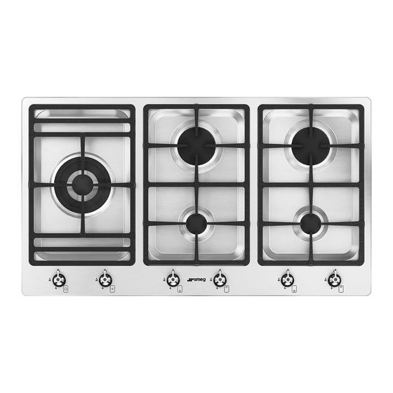
Page 8: Description
Description 2 Description 2.1 General Description 1. Control panel 2.2 Symbols 2. Auxiliary Burner (AUX) Cooking zones 3. Reduced Rapid Burner (RR) 4. Ultra-rapid burner internal crown (UR2 Rear int.) 5. Ultra-rapid burner external crown (UR2 ext.) Front 8. Right pan support grid 7. -
Page 9: Available Accessories
Description Burner knobs For lighting and adjusting the hob burners. Press and turn the knobs anti-clockwise to The pan support must be placed on the hob in order to light the relative burners. Turn the grid as shown in the figure above. knobs to the zone between the maximum In any case, pans with a diameter greater than 26 cm must be used solely on the... -
Page 10: Use
3 Use 3.2 First use 1. Remove any protective film from the 3.1 Instructions outside or inside of the appliance, including accessories. Improper use 2. Remove any labels (apart from the Danger of burns technical data plate) from accessories. 3. Remove and wash all the appliance •... - Page 11 Positioning the pan support grids Practical tips for using the hob The pan support grids are provided For better burner efficiency and to minimise unassembled on the hob. To position the gas consumption, use pans with lids and of pan support grids correctly, follow the suitable size for the burner, so that the instructions shown in figure.
- Page 12 Limitations on griddle use A few precautions are necessary if you wish to use a griddle: • Griddles must never protrude beyond the edge of the hob. • Teflon-coated aluminium griddles should be pre-heated empty for a maximum of 5 minutes in order to avoid damaging the appliance and the Teflon coating.
-
Page 13: Cleaning And Maintenance
Cleaning and maintenance 4 Cleaning and maintenance Food stains or residues Do not use steel sponges and sharp 4.1 Instructions scrapers as they will damage the surface. Use normal, non-abrasive products and a Improper use wooden or plastic tool, if necessary. Rinse Risk of damage to surfaces thoroughly and dry with a soft cloth or a microfibre cloth. - Page 14 Cleaning and maintenance Flame-spreader crowns and burner caps Igniters and thermocouples For correct operation the igniters and For easier cleaning, the flame-spreader crowns and the burner caps can be thermocouples must always be perfectly removed. Wash them in hot water and non- clean.
-
Page 15: Installation
Installation 5 Installation 5.2 Positioning in the counter top The following operation requires 5.1 Safety instructions building and/or carpentry work Heat production during appliance and must therefore be carried out operation by a competent tradesman. Risk of fire Installation can be carried out on various materials such as masonry, •... - Page 16 Installation To prevent liquids leaking between the 2. Place the hob on the insulating seal and frame of the hob and the worktop, carefully fix it to the supporting structure using the position the insulating seal provided (E) screws and fastening brackets before assembly.
- Page 17 Installation Fixing to the support structure: flush built- in model Create an opening with the dimensions shown in the figure in the countertop of the piece of furniture. L (mm) X (mm) Y (mm) This built-in model requires a 3mm deep recess to be cut in the worktop (detail “B”...
- Page 18 Installation • When fastening this appliance to the support structure, you are advised not to use mechanical or electrical screwdrivers and to exert moderate pressure manually on the fastening hardware. • Use the supplied brackets in all the fixing points. Once this has been done, fix the appliance This appliance can also be installed in a into position using the special brackets...
-
Page 19: Mounting
Installation Dimensions: Location of gas and 5.3 Mounting electrical connections (measurements Over built-in oven unit in mm) The clearance between the hob and the kitchen furniture or other installed appliances must be enough to ensure sufficient ventilation and air discharge. If installed above an oven, a space must be left between the bottom of the hob and the top of the appliance installed below. -
Page 20: Gas Connection
Installation 5.4 Gas connection On top of an empty kitchen unit or drawers Gas leak If there are other pieces of furniture (lateral Danger of explosion walls, drawers, etc.), dishwashers or fridges under the hob, a double-layer wooden • After carrying out any operation, check base must be installed at least 10 mm from that the tightening torque of gas the bottom of the hob to avoid any... - Page 21 Installation Connection with a steel hose Apply insulating material to the thread of connector 3, then tighten the steel hose 4 to Make the connection to the gas mains the connector 3. using a continuous wall steel hose whose specifications comply with the applicable standard.
- Page 22 Installation Connection with a rubber hose The hose connector 6 can also be screwed to the hose connector 7, depending on the Make the connection to the gas mains diameter of the gas hose used. After using a rubber hose whose specifications tightening the hose connectors, push the comply with current standards (verify that gas hose 5 onto the hose connector 6 or...
- Page 23 Installation Connection to LPG Room ventilation Use a pressure regulator and make the The appliance should be installed in rooms connection on the gas cylinder following that have a permanent air supply in the guidelines set out in the standards in accordance with the standards in force.
- Page 24 Installation Extraction of the combustion products When the job is complete, the installer must issue a certificate of conformity. The combustion products may be extracted 1 Extraction using a hood by means of hoods connected to a natural 2 Extraction without a hood draught chimney whose efficiency is certain or via forced extraction.
-
Page 25: Adaptation To Different Types Of Gas
Installation 5.5 Adaptation to different types of gas 3. Unscrew the burner nozzles using a 7 mm socket wrench and replace them In case of operation with other types of gas, according to the type of gas to be used the burner nozzles must be changed and (see the “Burner and nozzle the minimum flame adjusted on the gas... - Page 26 Installation Adjusting the minimum setting for natural 5. Turn the knob rapidly from the maximum or town gas to the minimum setting: The flame should not go out. Repeat the operation for all 1. Light the burner and turn it to the minimum gas cocks position.
- Page 27 Installation Gas types and Countries Gas types IT GB-IE FR-BE DE RU DK 1 Natural Gas G20 20 mbar • • • • • • • • • • G20/25 20/25 mbar 2 Natural Gas G20 25 mbar • 3 Natural Gas G25 25 mbar •...
- Page 28 Installation Burner and nozzle characteristics table 1 Natural Gas G20 – 20 mbar UR2 Int. UR2 Ext. Rated heating capacity (kW) 1.05 Nozzle diameter (1/100 mm) Reduced flow rate (W) 1600 Pre-chamber (printed on nozzle) 2 Natural Gas G20 – 25 mbar UR2 Int.
- Page 29 Installation 8 Natural gas G2.350 – 13 mbar UR2 Int. UR2 Ext. Rated heating capacity (kW) Nozzle diameter (1/100 mm) Reduced flow rate (W) 1600 Pre-chamber (printed on nozzle) 9 LPG G30/31 - 30/37 mbar UR2 Int. UR2 Ext. Rated heating capacity (kW) 1.05 Nozzle diameter (1/100 mm) Reduced flow rate (W)
-
Page 30: Electrical Connection
Installation 5.6 Electrical connection Perform the ground connection using a wire that is 20 mm longer than the other wires. Power voltage Pass the power supply cable Danger of electrocution through the back of the unit, taking care that it does not touch the •... -
Page 31: Instructions For The Installer
Installation Connection with plug and socket 5.7 Instructions for the installer • The plug must be accessible after Make sure that the plug and socket are of installation. Do not bend or trap the the same type. power cable. Avoid using adapters and shunts as these could cause overheating and a risk of •...
Need help?
Do you have a question about the PS906-5 and is the answer not in the manual?
Questions and answers